
Locally controlled hydraulic oil-containing sludge spiral conveying pump

A technology of screw conveying and hydraulic oil, applied in rotary piston pump, rotary piston/oscillating piston pump components, rotary piston/oscillating piston pump combination, etc., which can solve the problem of large labor demand and construction risks. High, time-consuming and labor-intensive

Inactive Publication Date: 2020-10-30
湖南天羽能源科技股份有限公司
View PDF6 Cites 1 Cited by
  • Summary
  • Abstract
  • Description
  • Claims
  • Application Information

AI Technical Summary

Problems solved by technology

[0004] (1) There is a large demand for labor and there is a risk of shortage
Due to the difficult working environment, currently only people over 50 years old can be hired to carry out the dredging manually. In the future, it will become increasingly difficult to find clearing personnel who are of the right age and willing to work, and the risk of labor shortage is very high;
[0005] (2) Long operating cycle
[0006] (3) High construction risk
[0007] (4) The process is not environmentally friendly
[0010] Therefore, material restrictions, size restrictions, weight restrictions, restrictions on explosion-proof requirements, and many other restrictions have made the tanker dredging operation a very traditional manual operation for a long time, which is time-consuming, laborious, unsafe and environmentally friendly.

Method used


Image

  • Locally controlled hydraulic oil-containing sludge spiral conveying pump
  • Locally controlled hydraulic oil-containing sludge spiral conveying pump
  • Locally controlled hydraulic oil-containing sludge spiral conveying pump

Examples


Embodiment Construction

[0032] The following will clearly and completely describe the technical solutions in the embodiments of the present invention with reference to the accompanying drawings in the embodiments of the present invention. Obviously, the described embodiments are only some, not all, embodiments of the present invention. Based on the embodiments of the present invention, all other embodiments obtained by persons of ordinary skill in the art without making creative efforts belong to the protection scope of the present invention.

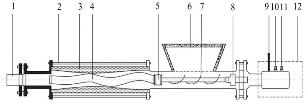
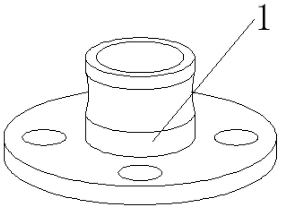
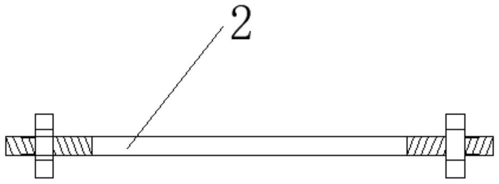
[0033] see Figure 1~4 , a locally controlled hydraulic type oily sludge screw conveying pump, including a pump main body; the pump main body includes a feed pipeline, a stator 3 and a discharge pipeline that are horizontally coaxially arranged and integrated, and the feed pipeline There is a feed end on the top, the feed end of the feed pipe is installed with a feed hopper 6 through a bolt assembly, and a rotating shaft with a spiral piece 7 is horizontally a...


PUM


Abstract

The invention discloses a locally controlled hydraulic oil-containing sludge spiral conveying pump. The locally controlled hydraulic oil-containing sludge spiral conveying pump comprises a pump main body; the pump body comprises a feeding pipeline, a stator and a discharging pipeline which are horizontally and coaxially arranged and are of an integrated structure, a feeding hopper is arranged on the feeding pipeline, the feeding hopper is installed at the feeding end of the feeding pipeline through a bolt assembly, and a rotating shaft with a spiral sheet is horizontally arranged in the feeding pipeline; the end part, away from the stator, of the feeding pipeline is connected with a hydraulic driving mechanism for driving the rotating shaft to work through a flange; and the other end of the rotating shaft is connected with the rotor in the inner cavity of the stator through a universal joint. The locally controlled hydraulic oil-containing sludge spiral conveying pump has the beneficial effects that oily sludge with various characteristics such as dryness, viscosity, dryness and thinness can be pumped, hydraulic driving is adopted, the explosion-proof requirement can be met, localcontrol can be realized, each interface is designed into a quick joint mode, namely, a pump outlet, a hydraulic motor interface and the like are designed into quick joints, a feeding trough is also designed into a detachable structure, and the equipment is convenient to disassemble and assemble.

Description

technical field [0001] The invention relates to a conveying pump, in particular to a locally controlled hydraulic oily sludge screw conveying pump, which belongs to the technical field of environmental protection machinery. Background technique [0002] During the daily operation of the tanker, there will be oil residue or sediment at the bottom and corners of the oil tank. After crude oil washing tank or water washing tank, there are still some remaining oil sludge that cannot be washed cleanly, and manual cleaning is required to remove the garbage inside. Wait until it is cleaned up to meet safety requirements. The process of cleaning up the remaining oil residue or garbage in the cabin is tank cleaning. According to the national environmental protection, the cargo owner’s cleaning requirements for the cabin of the ship that is changing the type of cargo, and the situation that the ship enters the factory for repairs, it is necessary to carry out the tank cleaning operatio...

Claims


Application Information

Patent Timeline
Patent Type & Authority Applications(China)
IPC IPC(8): F04C2/107F04C13/00F04C11/00F04C15/00
CPCF04C2/1073F04C2/1075F04C13/001F04C11/00F04C15/0057F04C15/00F04C2240/10F04C2240/20F04C2240/806
Inventor 陈云浩陈良福沈朝
Owner 湖南天羽能源科技股份有限公司
Learn More