Multi-stage cooling water system of coal fired power plant vacuum pump, and cooling method

A technology of cooling water system and coal-fired power station, which is applied in chemical technology research and energy fields, can solve the problems that the power plant coolant cannot meet the cooling demand of the vacuum pump, the temperature of the cooling water rises, and the cavitation of the vacuum pump, etc., so as to improve the overall heat exchange efficiency , reduce the extraction temperature, and reduce the effect of the heat exchange end difference of the system

Pending Publication Date: 2020-10-30
CENT SOUTHERN CHINA ELECTRIC POWER DESIGN INST CHINA POWER ENG CONSULTING GROUP CORP
View PDF0 Cites 2 Cited by
  • Summary
  • Abstract
  • Description
  • Claims
  • Application Information

AI Technical Summary

Problems solved by technology

However, in summer working conditions, the rise in temperature will lead to a simultaneous rise in the temperature of the above two cooling waters, and part of the power plant coolant cannot meet the cooling needs of the vacuum pump, resulting in serious operational accidents such as vacuum pump cavitation and even power plant shutdown

Method used


Image

  • Multi-stage cooling water system of coal fired power plant vacuum pump, and cooling method
  • Multi-stage cooling water system of coal fired power plant vacuum pump, and cooling method
  • Multi-stage cooling water system of coal fired power plant vacuum pump, and cooling method

Examples


Embodiment Construction

[0032] The implementation of the present invention will be described in detail below in conjunction with the accompanying drawings, but they do not constitute a limitation of the present invention, but are only examples, and will become clearer and easier to understand by illustrating the advantages of the present invention.

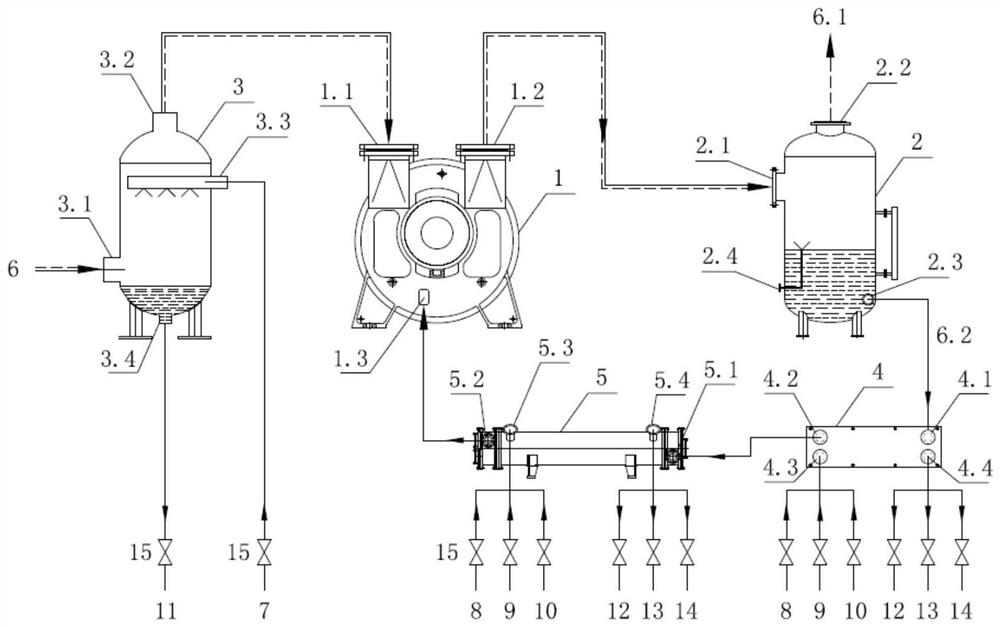
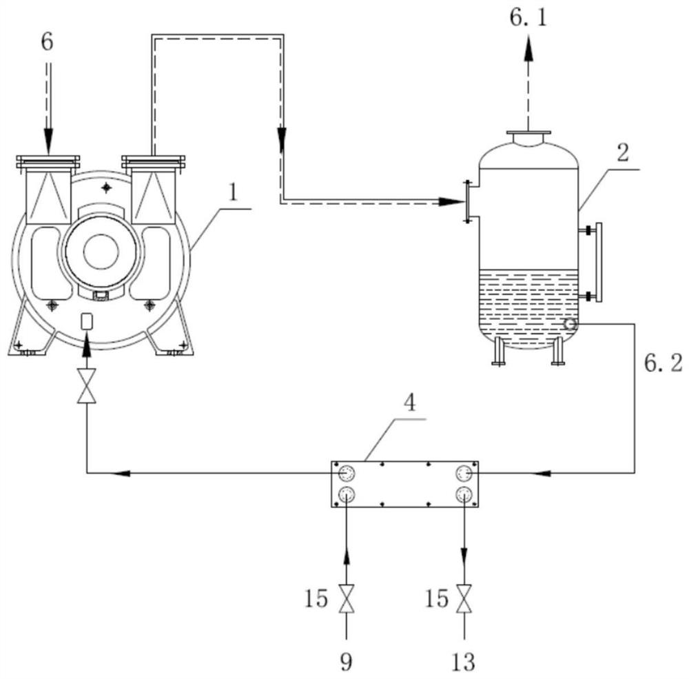
[0033] refer to Figure 1-4 Shown: a multi-stage cooling water system for a vacuum pump in a coal-fired power station of the present invention, which includes a vacuum pump body 1, a gas-water separator 2, a pre-cooler 3, a primary cooler 4, a secondary cooler 5, and a gas-water mixture 6. Exhaust 6.1, return working fluid 6.2, condensed water structure 7, closed circulating water structure 8, open circulating water structure 9, air conditioning chilled water structure 10, condensed water return structure 11, closed circulating water structure return water Structure 12, open circulating water return structure 13, air conditioner chilled water return stru...


PUM


Abstract

The invention discloses a multi-stage cooling water system of a coal fired power plant vacuum pump, and a cooling method. The system comprises two main body devices including a vacuum pump body (1), three stages of cooling devices including a gas-water separator (2), a pre-set cooler (3), a first-stage heat exchanger (4) and a second-stage heat exchanger (5), and four stages of cooling water sources including condensate water (7), a closed-type circulation water structure (8), open-type circulation water (9) and air conditioner freezing water (10). Among the four stages of cooling water sources, the condensate water (7) is injected into the pre-set cooler (3), and the rest cooling water sources with relatively high temperatures are injected into the first-stage heat exchanger (4), and thecooling water sources with relatively low temperatures are injected into the second-stage heat exchanger (5). The system and method disclosed by the invention overcome the defect that safety problemssuch as output insufficiency, cavitation and halting occur because cooling efficiency of the vacuum pump is not high under some working conditions; and the system and method have the advantages that cooling water temperatures of the vacuum pump can be efficiently adjusted by multiple stages in different seasons and under different temperatures and different working conditions.

Description

technical field [0001] The invention relates to the technical field of energy and chemical technology research, more specifically a multi-stage cooling water system and cooling method for a vacuum pump in a coal-fired power station. Background technique [0002] Liquid ring vacuum pumps are mainly used for the formation of vacuum. Due to their advantages of close to isothermal compression, insensitivity to dust, and the inhaled gas can entrain liquid or a large amount of water vapor, they are widely used in electric power, chemical industry, papermaking and other industries. Specifically in the power industry, vacuum pumps are mainly used to establish and maintain condenser vacuum. [0003] When the liquid ring pump is running, due to the release of mechanical energy, the condensation and heat release of the pumped gas will cause the temperature of the working fluid to rise continuously, which will cause cavitation in the pump body, reduce the performance of the liquid ring ...

Claims


Application Information

Patent Timeline
Patent Type & Authority Applications(China)
IPC IPC(8): F04C29/04F04C19/00F04C25/02
CPCF04C19/004F04C25/02F04C29/04
Inventor 桂本闵山山许婷赵瑞娥张黎仇晓龙张春琳祝培旺李宽宽李萱李志远王锐
Owner CENT SOUTHERN CHINA ELECTRIC POWER DESIGN INST CHINA POWER ENG CONSULTING GROUP CORP
Why Eureka
Try Eureka