Centrifugal fan and range hood using the centrifugal fan

A centrifugal fan and air inlet technology, which is applied in the field of centrifugal fans and range hoods, can solve problems such as increased air flow turbulence, decreased impeller working ability, and increased leakage flow, and achieves the solution of howling sound, reduction of volume loss, The effect of increasing drag

Active Publication Date: 2022-01-25
NINGBO FOTILE KITCHEN WARE CO LTD
View PDF11 Cites 0 Cited by
  • Summary
  • Abstract
  • Description
  • Claims
  • Application Information

AI Technical Summary

Problems solved by technology

[0004] In the existing multi-blade centrifugal fan system, since the air flow enters the volute from the axial direction, it needs to turn a relatively large angle to flow out from the radial direction of the impeller, which increases the degree of turbulence of the air flow; It is close to the front ring of the impeller, and the position between the two is prone to eddy currents, thus forming edge sounds (howling sounds are formed when the frequency is appropriate)
In addition, there are other problems in the cooperation between the collector and the impeller: when the axial clearance is too small, the airflow cannot quickly change from axial to radial flow after entering the impeller, so that the front end of the impeller forms a low-speed vortex flow, and the impeller’s The working ability decreases; when the axial clearance is appropriately increased, although the airflow entering the impeller can better complete the change of speed direction, reduce the low-speed vortex flow, and improve the working ability of the front end of the impeller, the leakage flow between the collector and the impeller will Slightly increased, the working ability of the impeller also decreased

Method used


Image

  • Centrifugal fan and range hood using the centrifugal fan
  • Centrifugal fan and range hood using the centrifugal fan
  • Centrifugal fan and range hood using the centrifugal fan

Examples


Embodiment 1

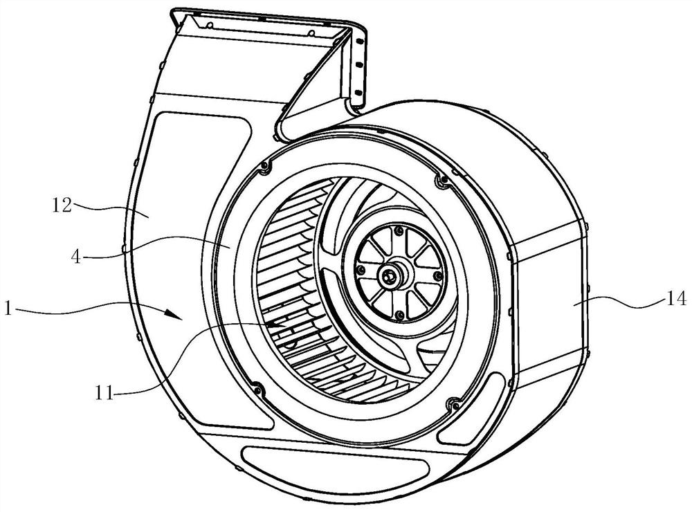
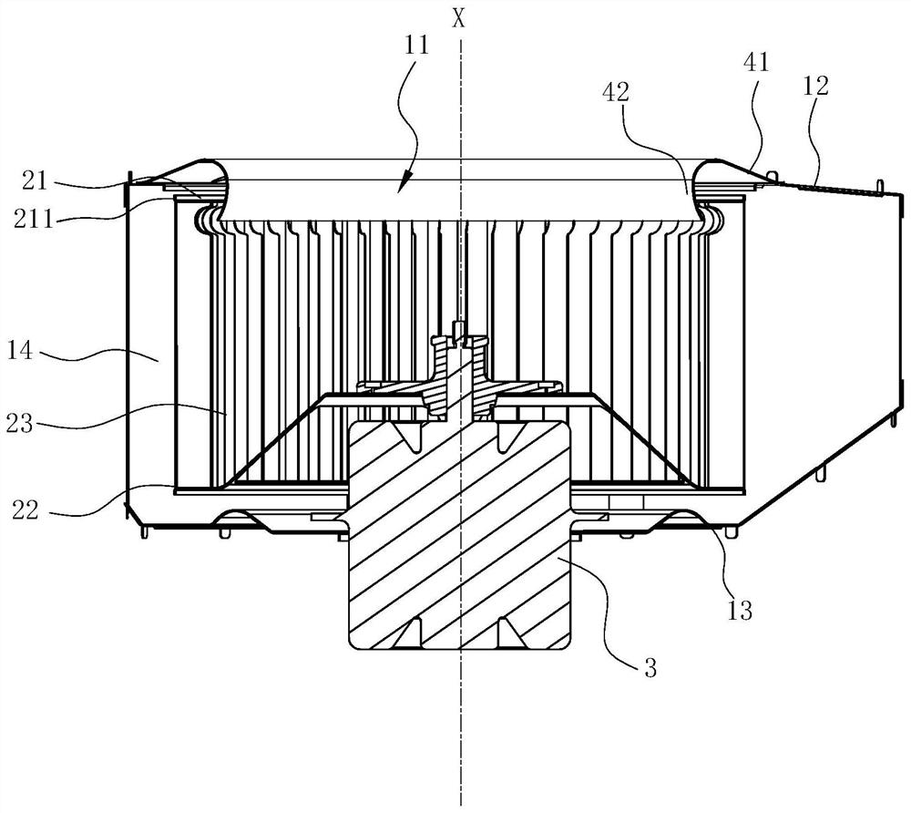
[0028] see figure 1 and figure 2 , a centrifugal fan that can be used as a power system for range hoods and other required fields. It includes a volute 1, an impeller 2 arranged in the volute 1 and a motor 3 for driving the impeller 2 to rotate. An air inlet 11 is formed on the volute 1 , and a current collector 4 is arranged at the air inlet 11 . The volute 1 includes a front cover 12 , a rear cover 13 , and an intermediate ring wall 14 arranged between the front cover 12 and the rear cover 13 . The above-mentioned air inlet 11 is opened on the front cover 12 .

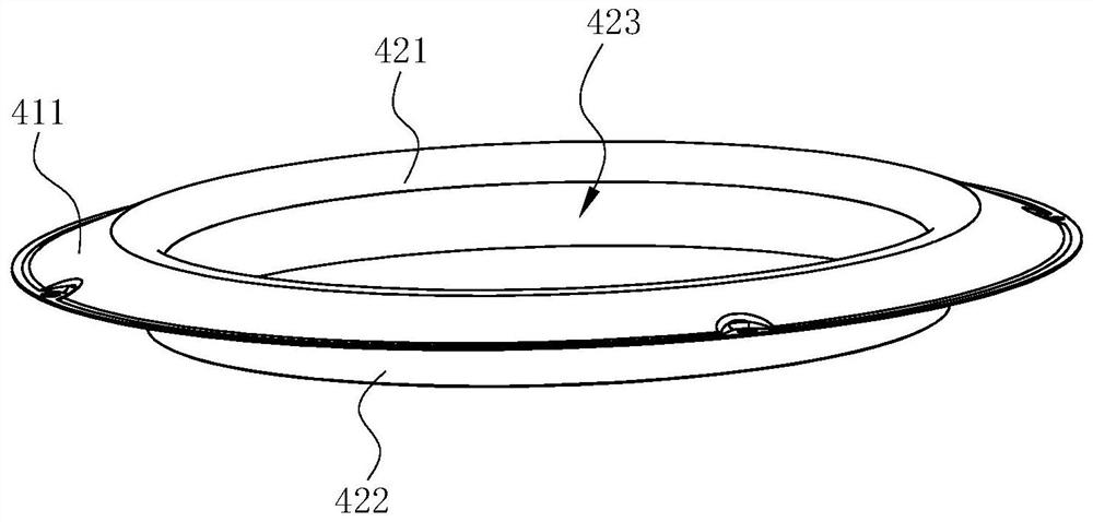
[0029] see Figure 2 ~ Figure 4 The collector 4 includes a mounting portion 41 connected to the volute 1 and a guide portion 42 for guiding the airflow. The mounting portion 41 is arranged on the outside of the volute 1 (the side away from the impeller 2), which is annular, It is connected and fixed with the outer periphery of the air inlet 11 of the volute 1. The guide part 42 is hollow cylindrical, and a vent...

Embodiment 2

[0036] see Figure 6 and Figure 7 , in this embodiment, the difference from the above-mentioned first embodiment is that a protrusion 43 is provided inside the axial guide part 422, and there are at least two protrusions 43, along which the axial guide part 422 Circumferentially spaced, preferably evenly spaced, prevents air flow from fluctuating at the tail end of the collector 4 . As a result, the resistance on the inner wall surface of the axial guide part 422 is increased, the large eddy caused by the impact of wind speed is slowed down, the sound is more comfortable when the airflow passes by, and the airflow entering along the axial guide part 422 is better. Sort out.

[0037] On the airflow path, the width (dimension in the circumferential direction) of the protrusion 43 increases gradually, thereby forming the shape of a bullet, so that the wind on the wall-adjacent surface can flow in a natural streamlined flow, avoiding loss caused by hitting the protrusion 43 . ...


PUM


Abstract

The invention discloses a centrifugal fan, which comprises a volute, an impeller arranged in the volute and a current collector, an air inlet is formed on the volute, the collector is arranged at the air inlet, the impeller and The current collector has a common axis, and the current collector includes an annular mounting part connected to the volute and a guide part for guiding the airflow, and the guide part includes a radially inner side extending inward from the mounting part. The radial guide part and the axial guide part extending from the radial inner side of the radial guide part through the air inlet to the inside of the volute, the impeller includes a front ring, a rear ring, and a front ring and a rear ring The blades between them are characterized in that: on the axial section of the current collector, the axial guide part is a curve that gradually expands radially outward from the end connected to the radial guide part toward the direction of the impeller, and every Each blade is formed with a recessed portion at the end connected to the front ring, and the recessed portion is formed by indenting from the radially inner side to the radially outer side of each blade.

Description

technical field [0001] The invention relates to a power system, in particular to a centrifugal fan and a range hood using the centrifugal fan. Background technique [0002] The multi-blade centrifugal fan has the characteristics of high pressure and low noise. Therefore, the current society generally uses the multi-blade centrifugal fan system as the power source, and uses the high-speed rotating impeller to complete the two functions of acting and filtering in the volute. As it is commonly used in range hoods, the oil smoke is sucked and exhausted through the multi-blade centrifugal fan installed inside the range hood. The multi-blade centrifugal fan includes a volute, an impeller installed in the volute and a motor that drives the impeller to rotate. When the impeller rotates, the The center of the fan generates negative pressure suction, sucking the fumes under the range hood into the fan, and after being accelerated by the fan, it is collected by the volute and guided ou...

Claims


Application Information

Patent Timeline
Patent Type & Authority Patents(China)
IPC IPC(8): F04D17/16F04D25/06F04D29/44F04D29/42F04D29/28F04D29/30F04D29/66F24C15/20
CPCF04D17/16F04D25/06F04D29/441F04D29/4233F04D29/283F04D29/30F04D29/663F04D29/667F24C15/20
Inventor 胡承杰王伟张鲁涛
Owner NINGBO FOTILE KITCHEN WARE CO LTD
Why Eureka
Try Eureka