Space twisting plastic impeller type well submersible pump

A space-distorted, impeller-type technology, applied to non-variable pumps, components of pumping devices for elastic fluids, pumps, etc., can solve problems such as the flow channel is not smooth enough, easy to leak, and the head is not enough , to achieve a smooth flow path, prevent leakage, and improve the sealing effect

Pending Publication Date: 2019-03-08
GUANGDONG RUIRONG PUMP IND
View PDF1 Cites 3 Cited by
  • Summary
  • Abstract
  • Description
  • Claims
  • Application Information

AI Technical Summary

Problems solved by technology

[0002] In the prior art, the main structure of the well submersible pump includes the casing and the water outlet pump head, check valve, bearing seat, sliding bearing, adjusting ring, multi-stage impeller assembly, coupling, water inlet, etc. installed in sequence from top to bottom. The base and the wire groove installed on the outer surface of the casing, the multi-stage impeller assembly includes a hexagonal pump shaft and a guide vane wheel, a shaft sleeve, an impeller, a guide casing and a spaced distribution of The pump shaft support frame, the guide vane and the impeller are injection molded welded parts, wherein the guide vane is welded by the guide vane seat and the shroud, the impeller is welded by the main impeller and the front cover of the impeller, the impeller and the guide The blades in the impeller are distributed in an involute helical shape, and the blade profile is composed of a circular arc and a straight line, as described in a previously applied invention patent "Impeller assembly in a well submersible pump", application number 201610673249.8 Like that, although its technical scheme has solved the problem that existing impeller flow is few, owing to there is intermittent between the top surface of impeller blade and the conical surface on the base and between the top surface of guide vane and the conical surface on the shroud. At the same time, there are several water outlet holes on the shroud, so that when the pump is in use, it is easy to leak under the pressure of the outlet water column with the increase of the speed, resulting in pressure loss, resulting in insufficient water pressure and insufficient lift. The projected arc edge of the upper main impeller is composed of a circular arc and a straight line. The flow path is not smooth enough, which will cause a little pressure loss. In addition, the angle between the straight line and the horizontal direction is the outlet angle is too small, so that the impeller The angle of the water outlet is more curved upwards, that is to say, the water flow thrown out by the centrifugal force of the impeller is relatively curved, and the pressure of the water flow will be weakened, resulting in a certain pressure loss. The water storage tank above the cover also has a certain resistance to the upward water flow in the pump, and will also cause a certain pressure loss. All the pressure losses will add up, which will bring a certain loss to the pump head, and the pump efficiency will also decrease. Head and efficiency, it is not necessary to use submersible pumps for wells with increased flow, but head and efficiency are also important indicators of water pumps. Compared with other existing technologies, if you want to achieve the same head, you need to increase the number of impeller stages. As a result, the cost is increased. Therefore, both the flow rate and the head must be high, and further improvement is needed.

Method used


Image

  • Space twisting plastic impeller type well submersible pump
  • Space twisting plastic impeller type well submersible pump
  • Space twisting plastic impeller type well submersible pump

Examples


Embodiment Construction

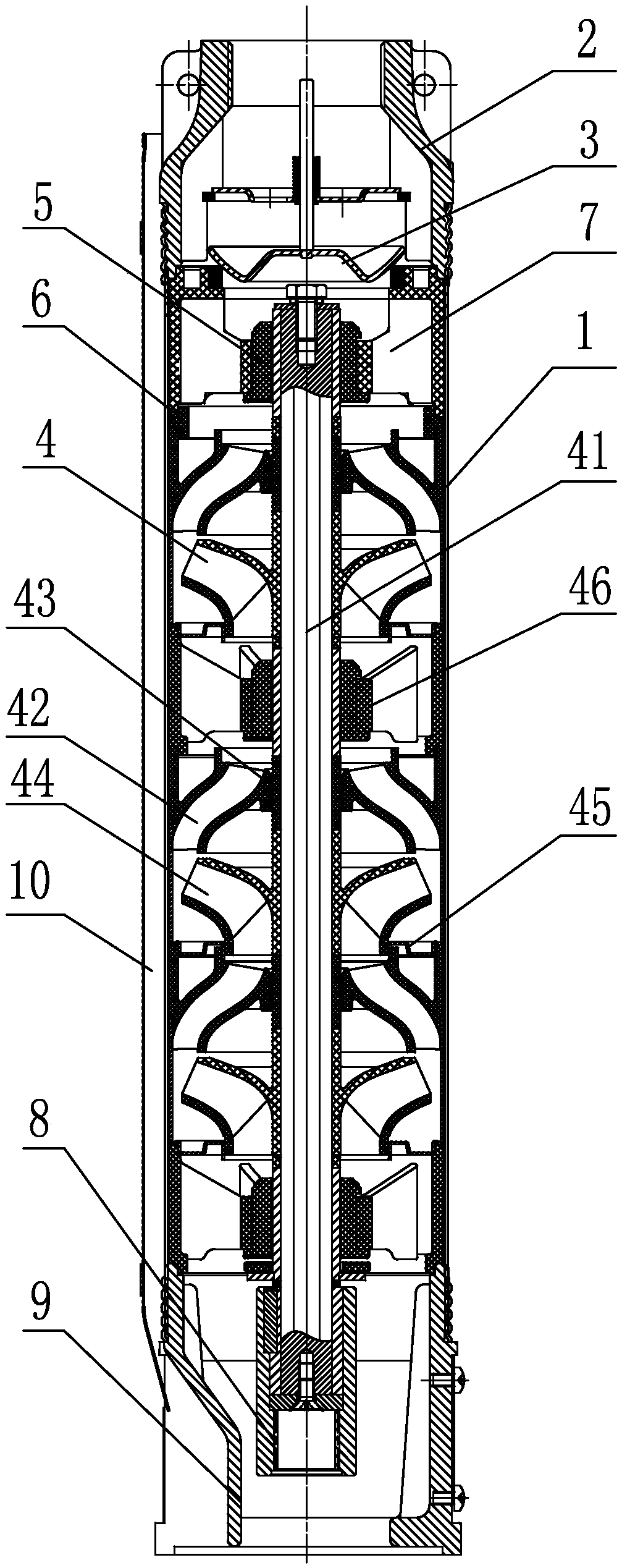
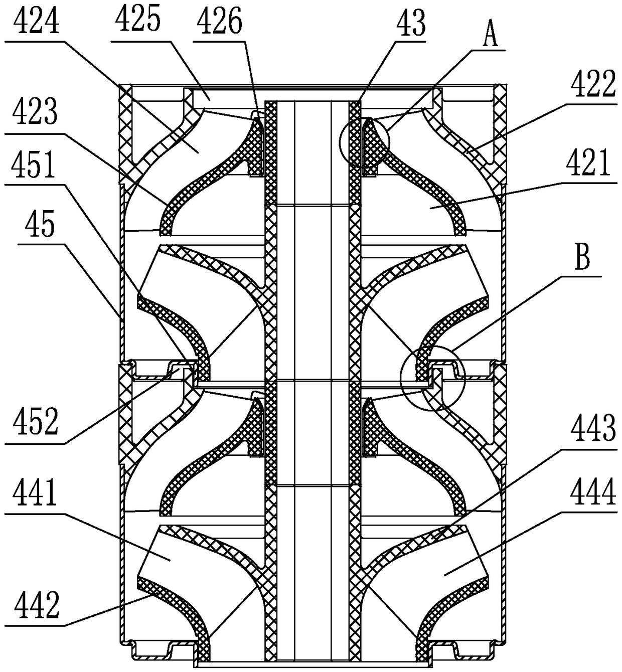
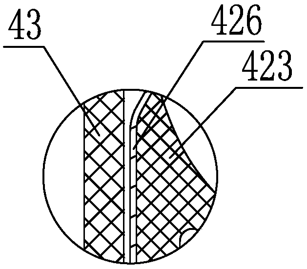
[0032] Depend on Figure 1-22 As shown, the embodiment of the space-distorted plastic impeller type well submersible pump of the present invention is: a casing 1 and a water outlet pump head 2, a check valve 3, a bearing seat 7, a sliding bearing 5, an adjusting Ring 6, multi-stage impeller assembly 4, coupling 8, water inlet base 9, and wire slot 10 installed on the outer surface of the housing. The multi-stage impeller assembly 4 includes a hexagonal pump shaft 41 and a multi-stage stack from top to bottom The guide vane wheel 42, the shaft sleeve 43, the impeller 44, the guide shell 45 and the pump shaft support frame 46 distributed at intervals are installed therein. The guide vane wheel 42 and the impeller 44 are all injection molded welded parts. Figures 9 to 13 As shown, the vane wheel 42 is welded by the vane seat 421 and the shroud 422, by Figures 18-21 As shown, the impeller 44 is welded by the main impeller 441 and the front cover plate 442 of the impeller. Fig...


PUM


Abstract

The invention discloses a space twisting plastic impeller type well submersible pump comprising a shell, a water outlet pump head, a check valve, a bearing seat, a sliding bearing, an adjusting ring,a multi-stage impeller assembly including a hexagonal pump shaft, a guiding impeller, a shaft sleeve, an impeller, a blower inlet casing and a pump shaft bearing frame, a coupling, a water inlet baseand a wire trough; and the guiding impeller is formed by welding a guide vane seat and a fairing which are obtained through injection molding, the impeller is formed by welding a main impeller and animpeller front cover plate which are obtained through injection molding, the guide vane seat includes a conical bottom cover designed according to the Bezier curve and seven spiral guide vanes, the main impeller includes a conical back cover plate designed according to the Bezier curve and six spiral blades, the spiral direction of the blades is opposite to the spiral direction of the guide vanes,the protruding water inlet of the blower inlet casing is in clearance fit with a water inlet of the impeller front cover plate, and an annular groove surrounding the protruding water inlet is in transition fit with the end of a water outlet of the fairing for positioning. The space twisting plastic impeller type well submersible pump has the beneficial effects of being large in flow rate and highin lift, being capable of reducing the pressure loss, improving the water pump efficiency and being low in cost.

Description

technical field [0001] The invention relates to a submersible pump for wells, in particular to a space-distorted plastic impeller type submersible pump for wells. Background technique [0002] In the prior art, the main structure of the well submersible pump includes the casing and the water outlet pump head, check valve, bearing seat, sliding bearing, adjusting ring, multi-stage impeller assembly, coupling, water inlet, etc. installed in sequence from top to bottom. The base and the wire groove installed on the outer surface of the casing, the multi-stage impeller assembly includes a hexagonal pump shaft and a guide vane wheel, a shaft sleeve, an impeller, a guide casing and a spaced distribution of The pump shaft support frame, the guide vane and the impeller are injection molded welded parts, wherein the guide vane is welded by the guide vane seat and the shroud, the impeller is welded by the main impeller and the front cover of the impeller, the impeller and the guide T...

Claims


Application Information

Patent Timeline
Patent Type & Authority Applications(China)
IPC IPC(8): F04D13/08F04D29/44F04D29/02
CPCF04D13/08F04D29/026F04D29/426
Inventor 陈国荣黄宇鹏林德照
Owner GUANGDONG RUIRONG PUMP IND
Why Eureka
Try Eureka