
Brake cylinder

A technology of brake cylinder and brake chamber, applied in the direction of brake actuator, fluid pressure actuating device, fluid pressure actuating system components, etc. Guaranteed, accelerated mitigation, time-reduced effects

Active Publication Date: 2020-10-30
CRRC QINGDAO SIFANG ROLLING STOCK RES INST +1
View PDF11 Cites 2 Cited by
  • Summary
  • Abstract
  • Description
  • Claims
  • Application Information

AI Technical Summary

Problems solved by technology

With the accumulation of ice, the seal between the brake chamber and the balance chamber will fail, causing the high-pressure gas in the brake chamber to enter the balance chamber, that is, the brake cylinder cannot maintain pressure, and the braking function will weaken or even fail, affecting driving safety.

Method used


Image

  • Brake cylinder
  • Brake cylinder
  • Brake cylinder

Examples


Embodiment Construction

[0043] The technical solutions of the present invention will be described in further detail below with reference to the accompanying drawings and embodiments.

[0044] The brake cylinder provided by the embodiment of the present invention can be used in the air brake system of rail transit vehicles, as the end actuator of the air brake system, connected with the brake caliper, and can convert the pressure of compressed air into a Mechanical thrust of the clamp. It should be noted that the compressed gas of the brake cylinder in the embodiment of the present invention is input through the brake pipeline.

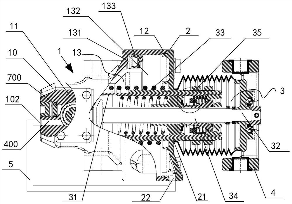
[0045] figure 1 The sectional structure diagram of the brake cylinder provided by the embodiment of the present invention. Such as figure 1 As shown, the brake cylinder includes: a cylinder body 1 , a cylinder head 2 , a power assembly 3 , a front end assembly 4 and a connecting pipe 5 .

[0046] The cylinder block 1 includes a gas circulation part 11 arranged at the gas ...


PUM


Abstract

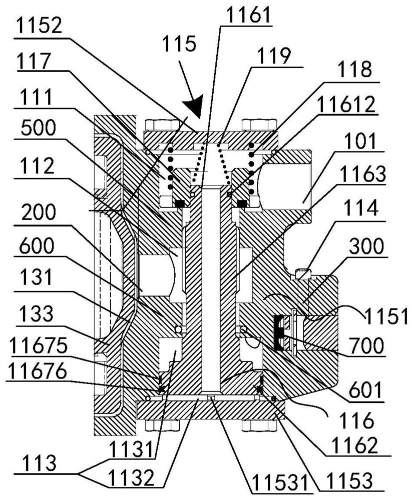
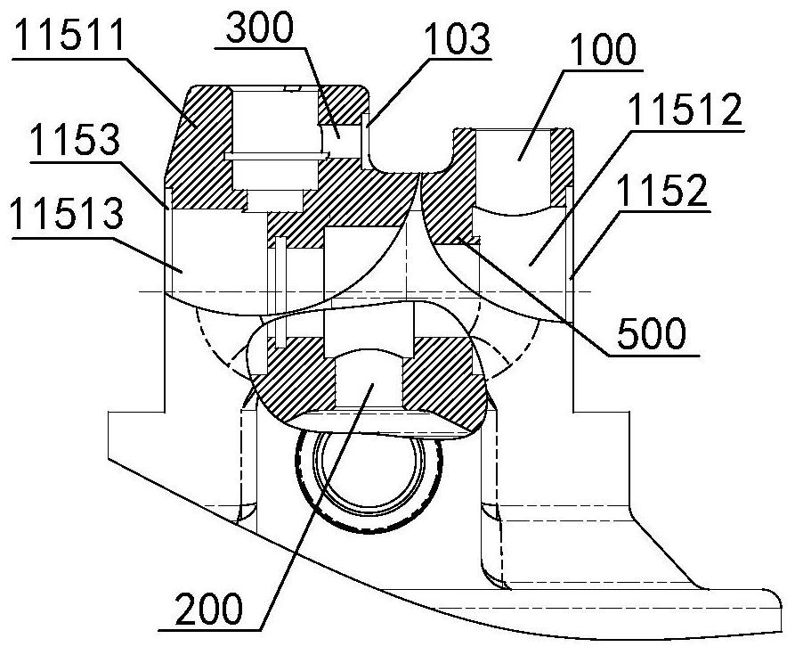
The invention relates to a brake cylinder. The brake cylinder comprises a cylinder body, a cylinder cover, a power assembly, a front assembly and a connecting pipe, wherein the cylinder body comprisesan air inlet cavity, a transition cavity, a respiratory cavity, an air inlet, a breathing connector and an air outlet; the cylinder body is divided into a brake chamber and a balance chamber by the power assembly; the cylinder cover covers the cylinder body; a breathing port is formed in the cylinder cover; the bottom end of the power assembly is stored in the cylinder body, and the top end protrudes from the cylinder body; the front assembly sleeves the top end of the power assembly; and one end of the connecting pipe is connected with the breathing connector, and the other end is connectedwith the breathing port. When the brake cylinder is braked, compressed gas which is input in a brake pipeline through the air inlet is conveyed to the brake chamber by the air inlet cavity through thetransition cavity, and the brake chamber is expanded, so that gas in the balance chamber is compressed and is discharged into the respiratory cavity through the connecting pipe and is discharged intothe atmosphere through the air outlet; when the brake cylinder is released, the brake chamber and the balance chamber are reset, and residual compressed gas in the transition cavity flows into the balance chamber through the respiratory cavity and the connecting pipe.

Description

technical field [0001] The invention relates to the technical field of vehicle brake devices, in particular to a brake cylinder. Background technique [0002] Rail transit vehicles are generally equipped with an air brake system as the most basic guarantee for speed regulation and parking. As the end actuator of the air brake system, the brake cylinder can convert the pressure of compressed air into mechanical thrust. After the mechanical thrust is amplified by the brake caliper, the kinetic energy is converted into heat energy through the interaction between the brake pad and the brake disc, thereby realizing the braking of the rolling stock. [0003] The brake cylinder is generally divided into two parts: the brake chamber and the balance chamber. During the braking and release process of the brake cylinder, the balance chamber mainly exchanges with the outside air through the respirator, so as to realize the balance with the atmospheric pressure. When braking, compress...

Claims


Application Information

Patent Timeline
Patent Type & Authority Applications(China)
IPC IPC(8): F16D65/18F15B13/02F15B21/00F16D121/04F16D125/02F16D125/04F16D125/16
CPCF15B13/02F15B13/027F15B21/008F16D65/18F16D2121/04F16D2125/02F16D2125/04F16D2125/16
Inventor 黄士伟王令军李培曙宋传云孔德鹏刁有彬
Owner CRRC QINGDAO SIFANG ROLLING STOCK RES INST
Learn More