Fire distributor with two variable fire hole airway characteristics

A fire device and fire distributor technology, which is applied in the field of burner fire distributors, can solve the problem of small proportion

Pending Publication Date: 2020-10-30
浙江惠厨节能科技有限公司
View PDF0 Cites 0 Cited by
  • Summary
  • Abstract
  • Description
  • Claims
  • Application Information

AI Technical Summary

Problems solved by technology

[0002] Burner firearms made of stainless steel plates are popular because their materials are not prone to oxidation and corrosion and have high sensory value. One of them is made of two sets of circular discs processed by stainless steel plates, and then alternately stacked and combined in sequence. Cylindrical fire divider, because a group of annular discs forming the fire hole and air passage are mostly formed by circumferential corrugated plates, and the other group of annular discs is formed by flat plates, and the two sets of annular discs are alternately stacked in sequence to form a divided The fire hole channel is formed between the front and back grooves of the firearm and the wave plate and the flat plate surface. Since the inlet and outlet geometric characteristics of this type of fire hole channel are almost the same, when the mixed gas circulates at the entrance and exit of the fire hole channel The resistance is almost the same, and the resistance of the mixed gas is almost the same when it flows through the inlet and outlet of the fire hole, so that the pressure and flow velocity of the mixed gas are almost the same when it flows out, and the pressure and flow velocity of the mixed gas flowing out from the outlet of the fire hole are the same, so that the initial period (can be Depending on the state) the combustion flame is evenly distributed near the exit of the fire hole, so that the overall state of the combustion flame in the initial stage (visible state) is in a regular circular cylindrical shape, and the overall state is in a regular circular cylindrical shape. The combustion flame determines the relative combustion chamber There is basically no work done by the initial flame in the central area. Experiments show that the volume of the uniform circular cylindrical visible combustion flame accounts for a relatively small proportion of the total volume of the combustion chamber, and the proportion of the relatively small volume is relatively concentrated. When the outer ring of the combustion chamber is close to the exit of the fire hole, it is difficult for the mixed gas that flows out relatively concentratedly to quickly and fully absorb the heat required for the combustion reaction in a larger area, and it is easy to reduce the combustion reaction speed and reaction intensity. The flame temperature is lower, and the quality of the combustion reaction is not high

Method used


Image

  • Fire distributor with two variable fire hole airway characteristics
  • Fire distributor with two variable fire hole airway characteristics
  • Fire distributor with two variable fire hole airway characteristics

Examples


Embodiment 1

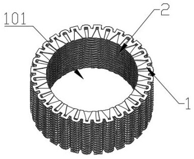
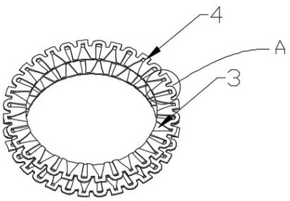
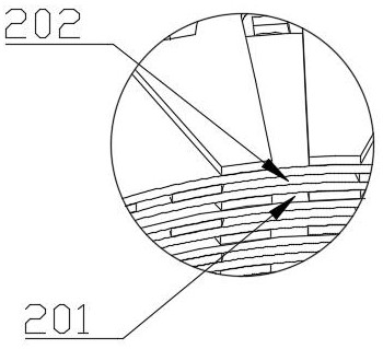
[0023]Embodiment 1: The first annular disc 3 and the second annular disc 4 form a firearm body, and the first air outlet 201 and the second air outlet 202 are arranged on the inner wall 1 of the fire distributor , the first air outlets 201 are arranged in a straight line in the vertical direction, and the second air outlets 202 are arranged in a straight line in the vertical direction. The width of the groove root 4011 gradually decreases, and the pressure of the mixed gas flow out of the first gas outlet 201 on the inner wall of the fire distributor 2 is high and the flow rate is fast; the width of the inner ring of the second comb tooth groove top 4022 gradually increases toward the second comb tooth groove root 4021 Large, and then the mixed gas flow out from the second gas outlet 202 has low pressure and slow flow rate, the mixed gas with low pressure and slow flow rate burns near the inner wall 2 of the fire distributor, and the mixed gas with high pressure and fast flow i...

Embodiment 2

[0024] Embodiment 2: The first annular disc 3 and the second annular disc 4 form a firearm body 1, and the first air outlet 201 and the second air outlet 202 are arranged on the inner wall 2 of the fire distributor Above, the first gas outlets 201 and the second gas outlets 202 are arranged vertically alternately and in a straight line. Compared with Example 1, in this arrangement, the flame is a mountain-shaped flame with an upward compact shape.

[0025] As another preferred embodiment of the present invention, the second annular disc 4 is provided with outer ring teeth 408, and the top of the outer ring teeth 408 is provided with outer ring tooth cusps 407. The outer ring tooth groove 406 and the outer ring tooth groove root 405 are arranged between the adjacent outer ring teeth 408. The shapes of the adjacent outer ring teeth 408 are different, which is convenient for distinguishing the first annular disk 3 and the second annular disk. Sheet 4 arrangement.

[0026] Specif...


PUM


Abstract

The invention relates to the technical field of gas stove fire distributors, and particularly discloses a fire distributor with two variable fire hole airway characteristics. The spacing between the top of a second comb tooth groove and the root of the second comb tooth groove gradually widens, the spacing between the top of a first comb tooth groove and the root of the first comb tooth groove gradually narrows, the gas flowing out of a second gas outlet has low pressure and low flow rate, the gas flowing out of a first gas outlet has high pressure and high flow rate, the mixed gas with lowerpressure and low flow rate burns near the inner wall of the fire distributor, the mixed gas with high pressure and high flow rate burns in a combustion chamber away from the fire distributor, the combustion flame is in the shape of mountain peaks and valleys and is in a high-low staggered form, and the high-low staggered flame and the swirling resident heat are intertwined and integrated more closely. The contact strength and contact surface between the mixed gas flow and the heat released by combustion are increased, the heat utilization efficiency is high, the combustion reaction space utilization rate of the combustion chamber is higher, and thus the combustion reaction speed, combustion reaction temperature and reaction intensity are improved.

Description

technical field [0001] The invention relates to the technical field of fire distributors for burners, and specifically discloses a fire distributor with the characteristics of two variable fire holes and air passages. Background technique [0002] Burner firearms made of stainless steel plates are popular because their materials are not prone to oxidation and corrosion and have high sensory value. One of them is made of two sets of circular discs processed by stainless steel plates, which are then alternately stacked and combined. Cylindrical fire divider, since a group of annular discs forming the fire hole and air passage are mostly formed by circumferential corrugated plates, and the other group of annular discs is formed by flat plates, and the two sets of annular discs are alternately stacked in sequence to form a divided The fire hole channel is formed between the front and back grooves of the firearm and the wave plate and the flat plate surface. Since the inlet and o...

Claims


Application Information

Patent Timeline
Patent Type & Authority Applications(China)
IPC IPC(8): F23D14/02F23D14/46F23D14/58F23D14/66
CPCF23D14/02F23D14/46F23D14/58F23D14/66Y02E20/34
Inventor 李芳春陈惠良
Owner 浙江惠厨节能科技有限公司
Why Eureka
Try Eureka