Harmonic current generating device and method for controlling stepless linear output of harmonic current

A technology for harmonic current generators, applied in the field of harmonic sources, can solve the problems of lack of harmonic current, large heat and loss, and lack of harmonic current, so as to achieve low total cost, low energy consumption, and improved key performance Effect

Pending Publication Date: 2020-10-30
江苏莱提电气股份有限公司
View PDF5 Cites 0 Cited by
  • Summary
  • Abstract
  • Description
  • Claims
  • Application Information

AI Technical Summary

Problems solved by technology

In this method, the harmonic components are uncontrollable under different conduction angles, which may lead to the loss of some harmonic currents, and cannot quantitatively control the magnitude of each harmonic current, nor can it accurately control the frequency of harmonics injected into the system.
The current method of obtaining harmonic current mainly has the following disadvantages: 1. The output harmonic current does not have the performance of stepless linear dynamic output, and debugging and use will vary with grid voltage, device temperature and conduction angle; 2. Manual adjustment Angle mode and manual start and stop can not automatically stabilize the harmonic current for a long time, and there is no automatic control of the upper computer control, etc.; 3. When the same harmonic current is issued, the heat and loss will be large, causing the harmonic voltage to be relatively large, and the operation 4. There is no design of load simulation unit for simulating and restoring various working conditions on site

Method used


Image

  • Harmonic current generating device and method for controlling stepless linear output of harmonic current
  • Harmonic current generating device and method for controlling stepless linear output of harmonic current
  • Harmonic current generating device and method for controlling stepless linear output of harmonic current

Examples


Embodiment Construction

[0029] The following will clearly and completely describe the technical solutions in the embodiments of the present invention with reference to the drawings in the embodiments of the present invention.

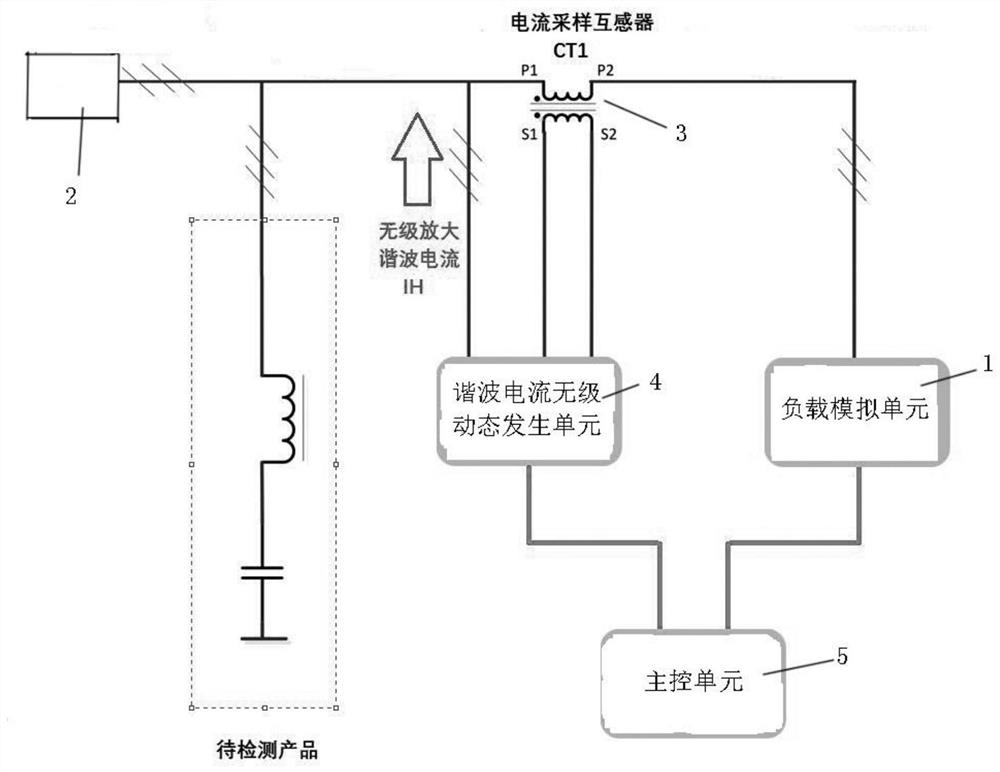
[0030] A harmonic current generating device of the present invention can provide large-capacity controllable harmonic current for reactive power compensation, harmonic filter products or other equipment connected to the power grid, and can restore the working conditions of analog equipment after on-site power supply Dedicated harmonic current source equipment can meet the requirements of manufacturers such as reactors, capacitors, compensation controllers, filters, complete cabinets, etc., for production testing, product output capability and compensation effect testing, or in harmonic environments when connected to the power grid. Practical values ​​such as working performance testing, or factory aging experiments, the common capacity of equipment is 100A ~ 600A, see figure 1...


PUM


Abstract

The invention provides a harmonic current generating device. The invention further provides a method for controlling stepless linear output of the harmonic current, the harmonic current and control over linear dynamic stepless output of the harmonic current are simulated, energy consumption is low, and the energy-saving effect is good. The method comprises the steps that a load simulation unit isconnected with a power grid and used for simulating and restoring various power utilization load working conditions on site; a sampling unit is connected with the power grid and load simulation unit and is used for sampling the load simulation unit; a harmonic current stepless dynamic generation unit is connected with the sampling unit and the load simulation unit; a harmonic current stepless dynamic generation unit calculates to obtain load harmonic current according to the current sampling data obtained by the sampling unit, and outputs supplementary harmonic current to the load simulation unit according to a difference value between the load harmonic current and a target harmonic current value; and a main control unit is connected with the harmonic current stepless dynamic generation unit and is used for sending a target harmonic current value at the current moment to the harmonic current stepless dynamic generation unit in real time.

Description

technical field [0001] The invention relates to the technical field of harmonic sources, in particular to a harmonic current generating device and a method for controlling stepless linear output of harmonic current. Background technique [0002] The traditional way to obtain a harmonic current source is to control the conduction angle and switch the resistance through a thyristor (thyristor). In this method, the harmonic components are uncontrollable under different conduction angles, which may lead to the loss of some harmonic currents, and cannot quantitatively control the magnitude of each harmonic current, nor can it accurately control the frequency of harmonics injected into the system. The current method of obtaining harmonic current mainly has the following disadvantages: 1. The output harmonic current does not have the performance of stepless linear dynamic output, and debugging and use will vary with grid voltage, device temperature and conduction angle; 2. Manual a...

Claims


Application Information

Patent Timeline
Patent Type & Authority Applications(China)
IPC IPC(8): G01R1/28G01R31/00
CPCG01R1/28G01R31/00
Inventor 马锋丁仕彬
Owner 江苏莱提电气股份有限公司
Why Eureka
Try Eureka