Supercharge Your Innovation With Domain-Expert AI Agents!

Optical device coupling soldering method

A welding method and optical device technology, applied in the coupling of optical waveguides, optical components, instruments, etc., can solve the problems of large power welding change, low yield rate, and difficult to uniform weld seam, so as to reduce welding change and avoid The effect of welding

Active Publication Date: 2022-03-11
CHENGDU SUPERXON COMM TECH CO LTD
View PDF0 Cites 0 Cited by
  • Summary
  • Abstract
  • Description
  • Claims
  • Application Information

AI Technical Summary

Problems solved by technology

In the prior art, there are certain welding gaps in the overlapping welding of BASE and the adjustment ring, and it is difficult to achieve uniform welding seam
The lap welding is placed in the last welding process of the three-piece coupling welding of optical devices, and the power welding becomes larger, so the yield rate is lower

Method used


Image

  • Optical device coupling soldering method
  • Optical device coupling soldering method
  • Optical device coupling soldering method

Examples


Embodiment Construction

[0026] The following will clearly and completely describe the technical solutions in the embodiments of the application with reference to the drawings in the embodiments of the application. Apparently, the described embodiments are only some of the embodiments of the application, not all of them. Based on the embodiments in this application, all other embodiments obtained by persons of ordinary skill in the art without creative efforts fall within the protection scope of this application.

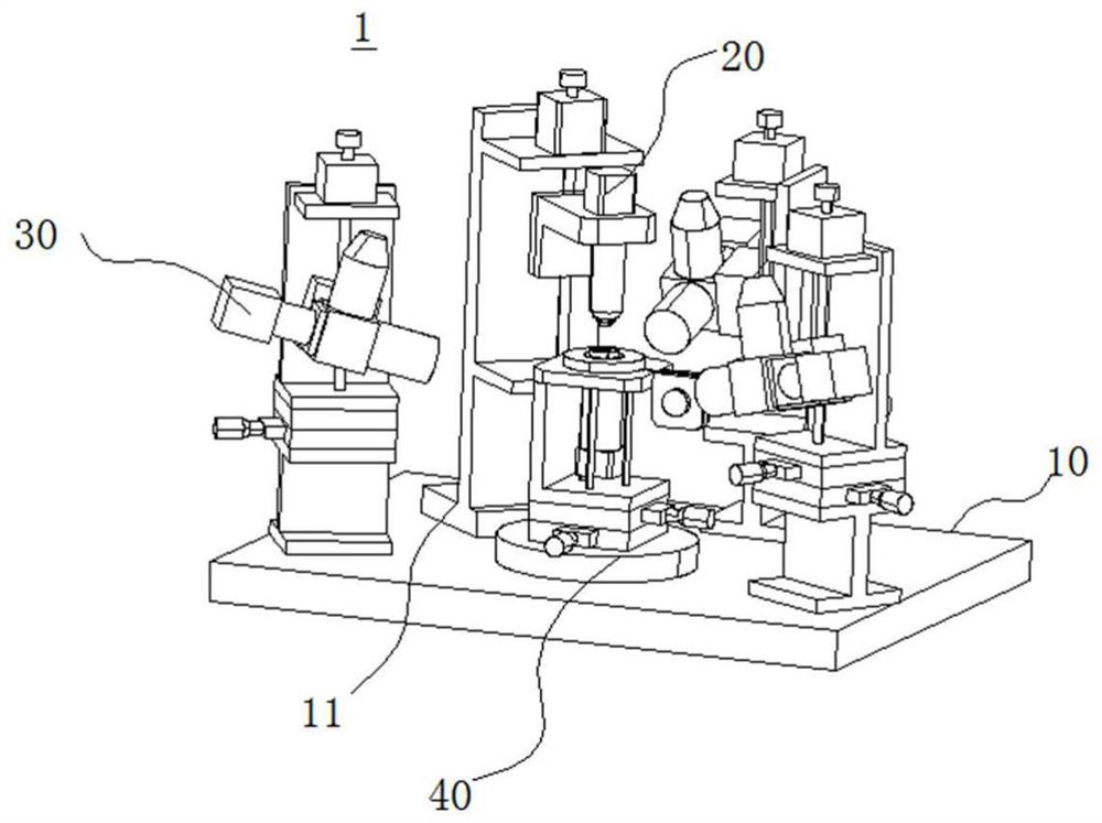
[0027] In the coupling welding production of optical devices, the welding transformation control is very important, which directly affects the production yield. As mentioned above, because the adjustment ring and the laser (LD) are first welded by penetration welding, and then the adjustment ring and the base (BASE) are welded by lap welding, there is a problem that the upper chuck and the lower chuck are coaxial The requirement of high degree of welding is high, which causes the problem of...


PUM


Abstract

An embodiment of the present application provides a coupling welding method for optical devices, including clamping the laser on the upper clamp, clamping the substrate on the lower clamp; providing an adjustment ring, and sleeve the adjustment ring on the protruding upper clamp of the laser part; adjust the upper chuck and the lower chuck to achieve the maximum coupling value between the laser and the substrate; lap weld the adjustment ring and the substrate with the first welding energy; lap weld the fixed adjustment ring and the substrate with the second welding energy, the second The second welding energy is greater than the first welding energy; the adjustment ring and the laser are welded in a penetrating welding manner. The method provided by the present application can reduce the influence of welding deformation caused by the coaxiality of the upper and lower chucks, simplify the welding process, and improve the welding efficiency.

Description

technical field [0001] The present application relates to the technical field of optical devices, in particular to an optical device coupling welding method. Background technique [0002] In the coupling welding production of optical devices, the welding transformation control is very important, which directly affects the production yield. Welding change = (post-welding optical power - pre-welding coupling optical power) / pre-welding coupling optical power, that is, the smaller the welding change, the better. The smaller the welding change, the smaller the optical power lost during welding. At present, in the optical device coupling welding process, usually after the coupling is completed, the adjustment ring and the laser (LD) are first welded by penetration welding, and then the adjustment ring and the base (BASE) are welded by lap welding. [0003] One of the reasons for the welding change is that since the lap welding is a horizontal welding, the coaxiality of the uppe...

Claims


Application Information

Patent Timeline
Patent Type & Authority Patents(China)
IPC IPC(8): G02B6/42
CPCG02B6/4296G02B6/4237
Inventor 奉光华
Owner CHENGDU SUPERXON COMM TECH CO LTD
Features
  • R&D
  • Intellectual Property
  • Life Sciences
  • Materials
  • Tech Scout
  • Unparalleled Data Quality
  • Higher Quality Content
  • 60% Fewer Hallucinations
Learn More