
Optical element driving device

A technology of driving device and optical element, applied in the direction of optical element, optics, projection device, etc., can solve the problems of unstable sensor detection, affecting the movement stroke, complex structure, etc.

Pending Publication Date: 2020-10-30
HENAN HAOZE ELECTRONICS
View PDF0 Cites 3 Cited by
  • Summary
  • Abstract
  • Description
  • Claims
  • Application Information

AI Technical Summary

Problems solved by technology

[0002] With the popularization of smart phones, the application range of mobile phone cameras is increasing. However, most of the sensors of mobile phone cameras are placed in the module outside the motor, and the side FPC uses a flexible circuit board, which causes problems such as warping. The detection is unstable. At the same time, the side FPC adopts a flexible circuit board. Uneven installation will affect the actual movement stroke. The vertical movement part of the carrier in the middle transmits the power of the bottom FPC to the upper reed and then to the coil on the carrier through the suspension wire. Internally, when the motor is impacted or after a long period of operation, the reliability of the suspension wire becomes lower, and problems such as breakage are prone to occur, resulting in the failure of the entire motor
In addition, there is usually a circuit board in the base, and the circuit board usually includes many layers. The external circuit and the focusing coil are connected through the circuit board and suspension wires. The structure is complex, the circuit is not simple enough, and the reliability is affected to a certain extent.

Method used


Image

  • Optical element driving device
  • Optical element driving device
  • Optical element driving device

Examples


Embodiment Construction

[0084] Preferred embodiments of the present invention will be described in detail below with reference to the accompanying drawings, so as to better understand the purpose, features and advantages of the present invention. It should be understood that the embodiments shown in the drawings are not intended to limit the scope of the present invention, but only to illustrate the essence of the technical solutions of the present invention.

[0085] In the following description, for the purposes of explaining the various disclosed embodiments, certain specific details are set forth in order to provide a thorough understanding of the various disclosed embodiments. One skilled in the relevant art will recognize, however, that an embodiment may be practiced without one or more of these specific details. In other instances, well-known devices, structures and techniques associated with the present application may not have been shown or described in detail in order to avoid unnecessarily...


PUM


Abstract

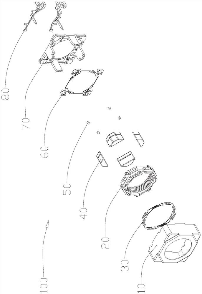
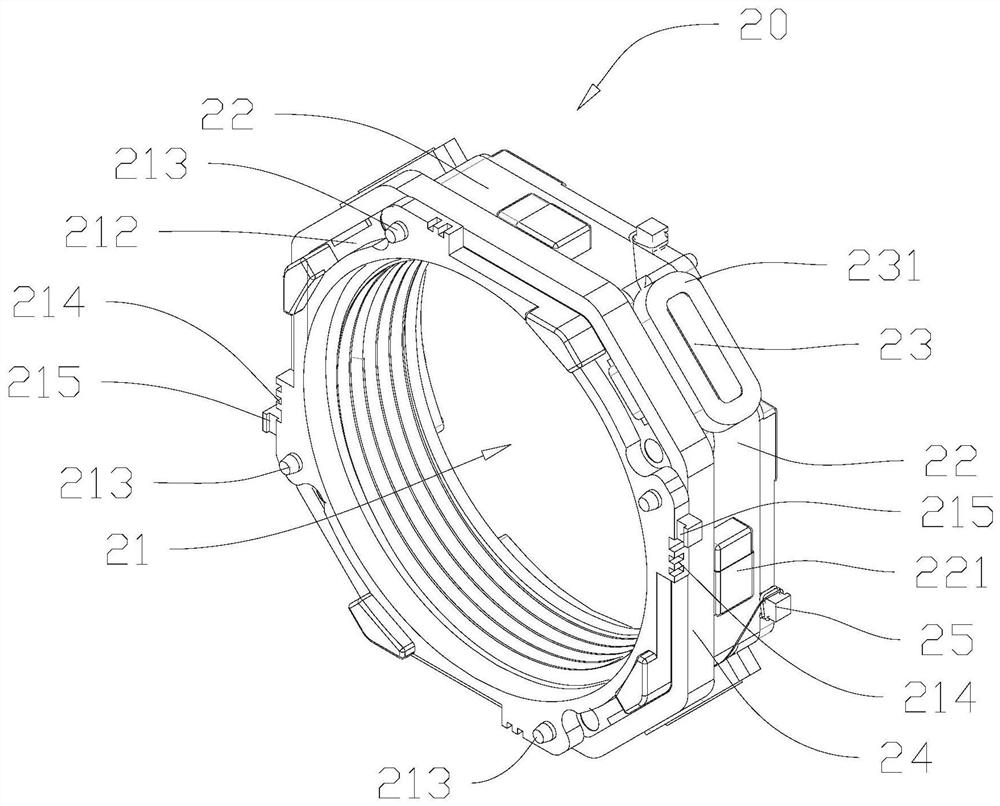
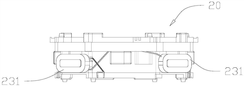
The invention discloses an optical element driving device. The optical element driving device comprises a shell, a carrier, an upper reed, a lower reed, a magnet group and a base. The carrier is usedfor installing a lens and is provided with a first coil and a second coil. The magnet group is arranged on the inner wall of the shell and is correspondingly matched with the first coil and the secondcoil on the carrier. The base comprises a bottom plate and a protruding part extending from the bottom plate to the top of the shell. The upper reed enables the upper surface of the carrier to be movably connected with the end face of the protruding part of the base, the lower reed enables the lower surface of the carrier to be movably connected with the bottom plate of the base, the base is further provided with a base embedded metal sheet, and the base embedded metal sheet enables the first coil and the second coil to be connected with an external circuit. The optical element driving devicehas the advantages of being simple in structure, low in cost, high in reliability and the like.

Description

technical field [0001] The invention relates to the technical field of optical imaging equipment, in particular to an optical element driving device. Background technique [0002] With the popularization of smart phones, the application range of mobile phone cameras is increasing. However, most of the sensors of mobile phone cameras are placed in the module outside the motor, and the side FPC uses a flexible circuit board, which causes problems such as warping. The detection is unstable. At the same time, the side FPC adopts a flexible circuit board. Uneven installation will affect the actual movement stroke. The vertical movement part of the carrier in the middle transmits the power of the bottom FPC to the upper reed and then to the coil on the carrier through the suspension wire. Internally, when the motor is impacted or after a long period of operation, the reliability of the suspension wire becomes low, and problems such as breakage are prone to occur, resulting in the ...

Claims


Application Information

Patent Timeline
Patent Type & Authority Applications(China)
IPC IPC(8): G02B7/08G03B5/00G03B13/34
CPCG02B7/08G03B5/00G03B13/34
Inventor 汪仁德林聪彭坤刘富泉吕新科其他发明人请求不公开姓名
Owner HENAN HAOZE ELECTRONICS
Learn More