Test method for determining unbalance loading deflection of box girder bridge based on single-girder finite element model
A test method and finite element technology are applied in the test field of determining the eccentric load deflection of a box girder bridge based on a single-girder finite element model, which can solve problems such as calculation distortion of eccentric load deflection, difficult calculation methods, and inconsistencies in actual displacement. Achieve the effects of reducing time and labor costs, wide applicability, and reliable results
Active Publication Date: 2020-10-30
GUANGXI TRANSPORTATION SCI & TECH GRP CO LTD +2
View PDF10 Cites 3 Cited by
- Summary
- Abstract
- Description
- Claims
- Application Information
AI Technical Summary
Problems solved by technology
The eccentric pressure method is a method based on the two assumptions of the approximate absolute rigidity of the beam and the neglect of the torsional stiffness of the main beam. The modified eccentric pressure method considers the torsional stiffness of the main beam compared with the eccentric pressure method. Both methods are Deduced from the calculation model of the ribbed girder bridge, it is quite different from the force and deformation of the closed box section, which leads to the distortion of the calculation of the partial load deflection
Therefore, the l
Method used
View moreImage
Smart ImageViewing Examples
Examples
 PUM
| Property | Measurement | Unit |
|---|---|---|
| Torsion angle | aaaaa | aaaaa |
Abstract
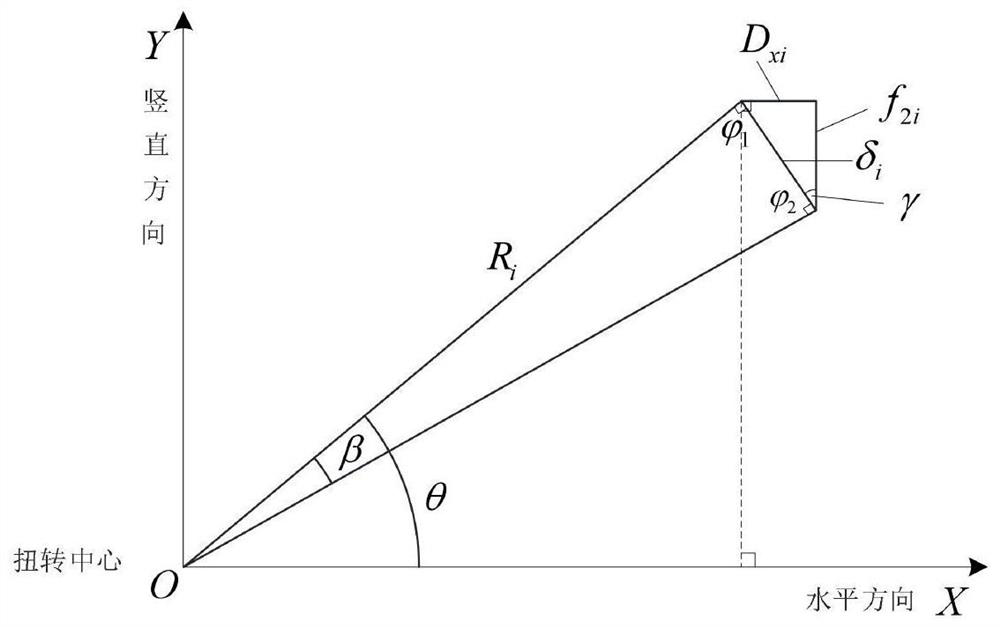
The invention relates to a static load test method for bridge deflection, and discloses a test method for determining the unbalance loading deflection of a box girder bridge based on a single-girder finite element model, and the method comprises the steps: calculating the overall deflection and torsion angle of a control cross section of a box girder under an eccentric test load based on the single-girder finite element model, and calculating a cross section deflection lateral distribution value through the geometrical relation between a torsion center and a deflection measurement point. Compared with other methods, the method has the advantages of simplicity, high efficiency and reliable result, can effectively reduce the time and labor cost, and reduces the energy consumption; the methodis applied to a bridge static load test, can cope with field loading and measurement point position adjustment at any time, responds to the requirement for rapid modification of a test scheme, avoidshysteresis quality of large finite element calculation and analysis, and facilitates real-time judgment of the bearing capacity condition and the structural safety of the concrete box girder bridge structure.
Description
technical field [0001] The invention belongs to a static load test method for bridge deflection, in particular to a test method for determining the eccentric load deflection of a box girder bridge based on a single beam finite element model. Background technique [0002] The bridge static load test is a complicated bridge bearing capacity appraisal work, and the calculation of the partial load deflection of the structure under the load is an important content. According to the control load determined before the test, the test load that produces equivalent internal force or deformation on the structural control section is calculated, and the test load is applied to the bridge structure in stages. By detecting the static response of the structure at the test position (such as stress (change), displacement, etc. , rotation angle, etc.) is a common method for judging the mechanical performance and bearing capacity of the structure by comparing it with the theoretical calculation...
Claims
Login to View More Application Information
Patent Timeline
 IPC IPC(8): G06F30/23G06F30/13G06F119/14
CPCG06F30/13G06F30/23G06F2119/14
Inventor 梁茜雪马耀宗王伟芳朱勇郝天之
Owner GUANGXI TRANSPORTATION SCI & TECH GRP CO LTD
Features
- R&D
- Intellectual Property
- Life Sciences
- Materials
- Tech Scout
- Unparalleled Data Quality
- Higher Quality Content
- 60% Fewer Hallucinations
Learn More Browse by: Latest US Patents, China's latest patents, Technical Efficacy Thesaurus, Application Domain, Technology Topic, Popular Technical Reports.
© 2025 PatSnap. All rights reserved.Legal|Privacy policy|Modern Slavery Act Transparency Statement|Sitemap|About US| Contact US: help@patsnap.com


