
A visual counting and positioning method for electronic components

A technology of electronic components and positioning methods, which is applied in calculation, image data processing, image analysis, etc., can solve problems such as excessive adhesion of electronic components, large differences in size and shape of electronic components, and influence on counting accuracy, so as to achieve accurate counting The effect of high rate and good robustness

Active Publication Date: 2022-03-22
XI AN JIAOTONG UNIV
View PDF8 Cites 0 Cited by
  • Summary
  • Abstract
  • Description
  • Claims
  • Application Information

AI Technical Summary

Problems solved by technology

[0004] The purpose of the present invention is to propose a visual counting and positioning method for electronic components to address the deficiencies in the existing electronic component counting and positioning methods based on traditional image processing technology. The excessive adhesion between some electronic components affects the counting accuracy. Using a model and a set of parameters to complete the electronic component counting task, this method has extremely high accuracy and robustness

Method used


Image

  • A visual counting and positioning method for electronic components
  • A visual counting and positioning method for electronic components
  • A visual counting and positioning method for electronic components

Examples


Embodiment Construction

[0030] The specific details in each step of the present invention will be described in detail below in conjunction with the accompanying drawings.

[0031] The present invention proposes a visual counting and positioning method of electronic components, the whole process of the method is as follows figure 1 shown.

[0032] The method mainly includes the following steps:

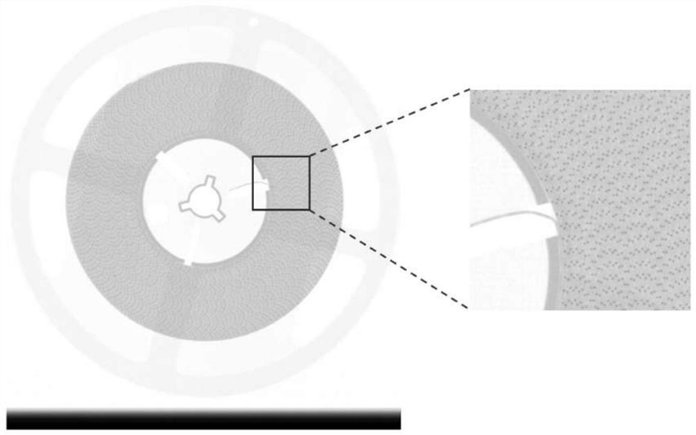
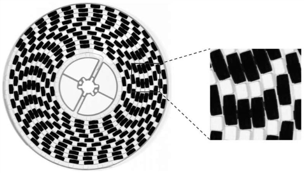
[0033] Step A: After obtaining the electronic component images taken by the X-Ray pointing machine, select some images and randomly crop them into images of the same size, as shown in Figure 2(a) for smaller electronic components, and Figure 2(b) for smaller electronic components Large electronic components, as shown in Figure 2(c), are electrons with serious adhesion. Each image of the component contains multiple electronic components, and the position of the center of gravity of all electronic components in each image is marked with pixel coordinates. The marked The images constitute the training image se...


PUM


Abstract

The invention discloses a visual counting and positioning method for electronic components, which comprises the following steps: 1. Select part of images, mark the center of gravity of electronic components and make a training image set; 2. Build a neural network model, use the training image set to train and save the neural network. Network model; 3. For an image other than a training image set, first preprocess, detect and cut out the black border; detect the outer circle and inner circle of the area where the electronic component is located; crop the smallest circumscribed square area of ​​the outer circle into an image Then input the neural network model in turn to obtain the density map matrix set; finally, after post-processing, the density map matrix is ​​merged; calculate the connected area between the outer circle and the inner circle of the density map matrix after the merger, and obtain the electronic component in the electronic component image Count and locate results. The method of the invention can solve the problems that the size and shape of the electronic components are too large and the adhesion between some electronic components is too large to affect the counting accuracy.

Description

technical field [0001] The invention belongs to the application field of computer vision, and specifically proposes a visual counting and positioning method for electronic components. Background technique [0002] With the rapid development of the electronic information industry, all kinds of electronic products appear in people's field of vision. Most electronic products are controlled by circuit boards, and circuit boards are inseparable from electronic components such as various capacitors, resistors, and inductors. Its production technology mainly adopts high-speed surface mount technology. During this process, the utilization rate of electronic components such as capacitors and resistors is extremely high. Therefore, SMT manufacturers have extremely high requirements for updating statistics of electronic components and other materials. [0003] Traditional counting of electronic components mostly adopts weighing or manual counting, which is not only inefficient but als...

Claims


Application Information

Patent Timeline
Patent Type & Authority Patents(China)
IPC IPC(8): G06T7/73G06T7/11G06T7/194G06T7/62G06N3/04
CPCG06T7/74G06T7/11G06T7/194G06T7/62G06T2207/10004G06T2207/20081G06T2207/20084G06T2207/20132G06T2207/30242G06N3/045
Inventor 宋永红王宏达李俞张元林
Owner XI AN JIAOTONG UNIV
Learn More