
Heat dissipation module

A technology of heat dissipation module and heat dissipation fin group, which is applied in the direction of electrical components, electric solid devices, circuits, etc., and can solve the problems of poor heat dissipation efficiency of heat dissipation modules

Pending Publication Date: 2020-10-30
SUNON ELECTRONICS KUNSHAN
View PDF0 Cites 0 Cited by
  • Summary
  • Abstract
  • Description
  • Claims
  • Application Information

AI Technical Summary

Problems solved by technology

[0003] However, the heat pipe of the existing heat dissipation module transfers heat by penetrating through the heat dissipation fin group. The heat dissipation fin group must be exposed, resulting in poor heat dissipation efficiency of the heat dissipation module at the bent structure

Method used


Image

  • Heat dissipation module
  • Heat dissipation module
  • Heat dissipation module

Examples


Embodiment Construction

[0047] In order to make the above-mentioned and other objects, features and advantages of the present invention more obvious and understandable, the preferred embodiments of the present invention are listed below, together with the accompanying drawings, and are described in detail as follows:

[0048] Directionality or similar terms used throughout the invention, such as "front", "rear", "left", "right", "upper (top)", "lower (bottom)", "inner", "outer" , "side", etc., mainly refer to the directions of the drawings, and each direction or its approximate terms are only used to assist in explaining and understanding the various embodiments of the present invention, and are not intended to limit the present invention.

[0049] The elements and components described throughout the present invention use the quantifier "a" or "an" only for convenience and to provide the usual meaning of the scope of the present invention; in the present invention, it should be interpreted as includin...


PUM


Abstract

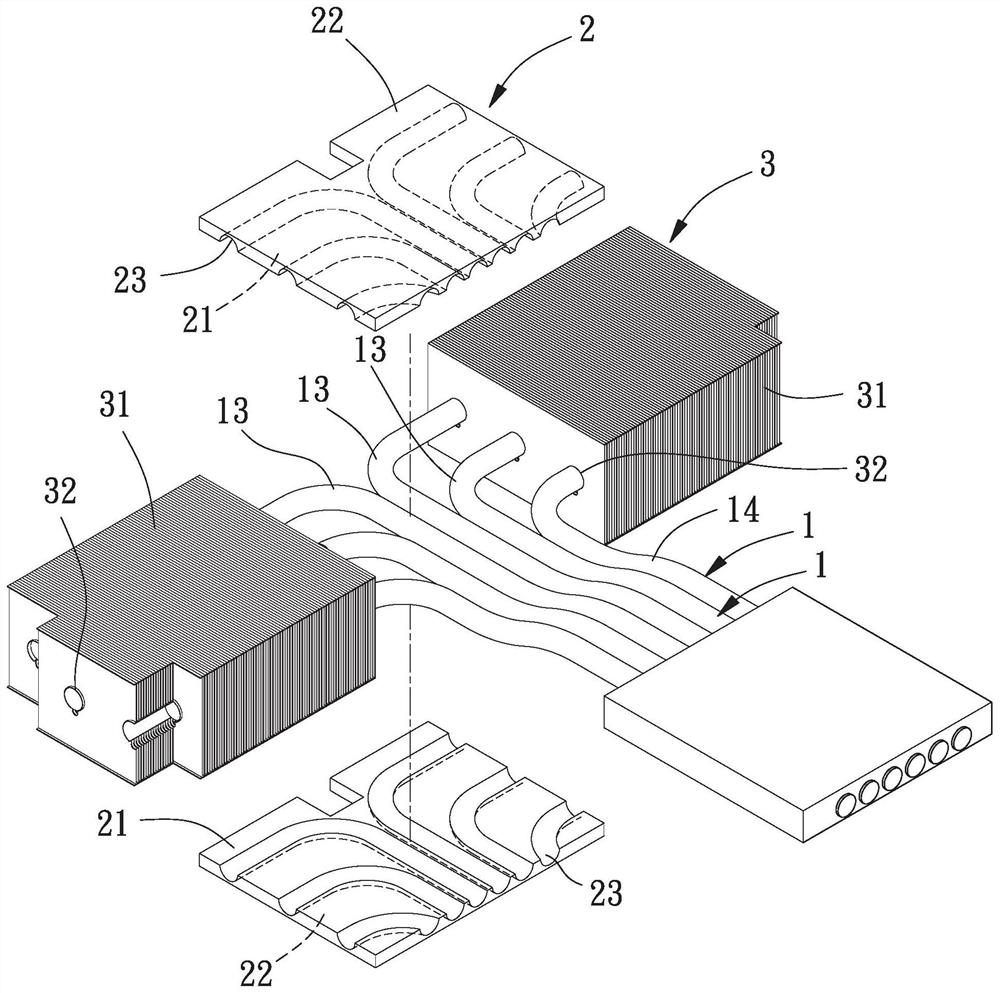
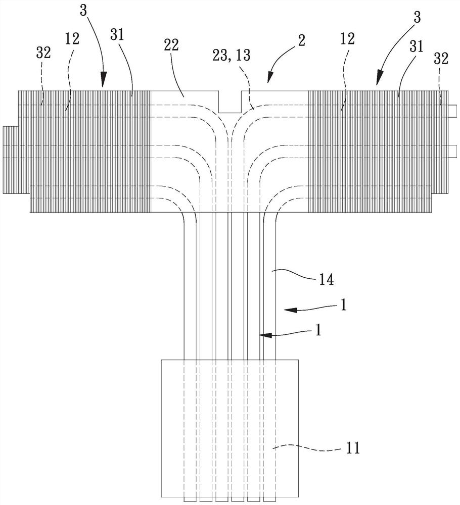
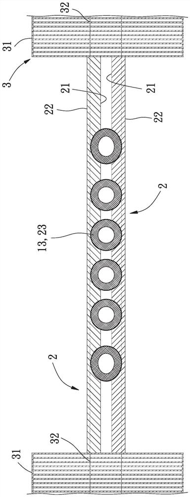
A heat dissipation module is used for solving the problem that the heat dissipation efficiency is poor due to the fact that a bent structure of an existing heat dissipation module is exposed, and comprises at least one heat pipe which is provided with a bent part located between an evaporation part and a condensation part; the at least one heat conduction plate is connected with the bent part of the heat pipe; and the radiating fin group is positioned at the condensation part of the heat pipe.

Description

technical field [0001] The invention relates to a heat dissipation module, in particular to a heat dissipation module capable of dissipating heat through heat transfer of heat pipes. Background technique [0002] The existing electronic components such as the central processing unit will generate a large amount of heat energy during operation, which will cause the temperature of itself to rise, so a heat dissipation module will be added to the electronic components, and the existing heat dissipation module uses a heat sink to use The heat generated by the electronic component is absorbed, and the absorbed heat is introduced into a heat dissipation fin group through a heat pipe to dissipate the heat, so that the heat dissipation module can dissipate heat from the electronic component. [0003] However, the heat pipe of the existing heat dissipation module transfers heat by penetrating through the heat dissipation fin group. The set of cooling fins must be exposed, resulting ...

Claims


Application Information

Patent Timeline
IPC IPC(8): H01L23/427H01L23/367
CPCH01L23/3672H01L23/427
Inventor 洪银树廖津均古惟仁
Owner SUNON ELECTRONICS KUNSHAN
Learn More