Vertical integrated unit diode chip

A technology of integrating cells and diodes, applied in electrical components, electro-solid devices, circuits, etc., to solve problems such as LED light efficiency, heat dissipation and stability limitations

Pending Publication Date: 2020-10-30
纳微朗科技(深圳)有限公司
View PDF7 Cites 0 Cited by
  • Summary
  • Abstract
  • Description
  • Claims
  • Application Information

AI Technical Summary

Problems solved by technology

Therefore, LED light efficiency, heat dissipation ...

Method used


Image

  • Vertical integrated unit diode chip
  • Vertical integrated unit diode chip
  • Vertical integrated unit diode chip

Examples


Embodiment 1

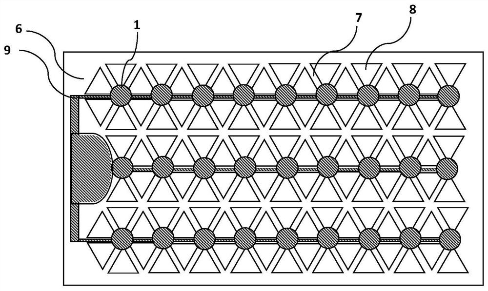
[0051] This embodiment provides a vertically integrated unit diode chip, including: a second conductivity type electrode 1 , a diode mesa structure 6 , a trench 7 , a diode unit 8 and an electrode line 9 .

[0052] Such as image 3 As shown, the diode mesa structure includes 6 rows of 102 equally sized and uniformly distributed triangular diode units, and the length of the diode units along the x-axis direction is 40 microns. The diode mesa structure adopts a triangular arrangement, and the size of the mesa structure is smaller than the current diffusion length. The diode units are triangular in shape and distributed according to a uniform symmetrical arrangement. The electrode wire is an electrode connecting wire between diode units, the width of the electrode wire is 0.001-20 microns, and the thickness is 0.001-10 microns.

[0053] Such as Figure 4 As shown, the diode mesa structure includes 6 rows of 6 rectangular diode units with uniform sizes, and the length of the di...

Embodiment 2

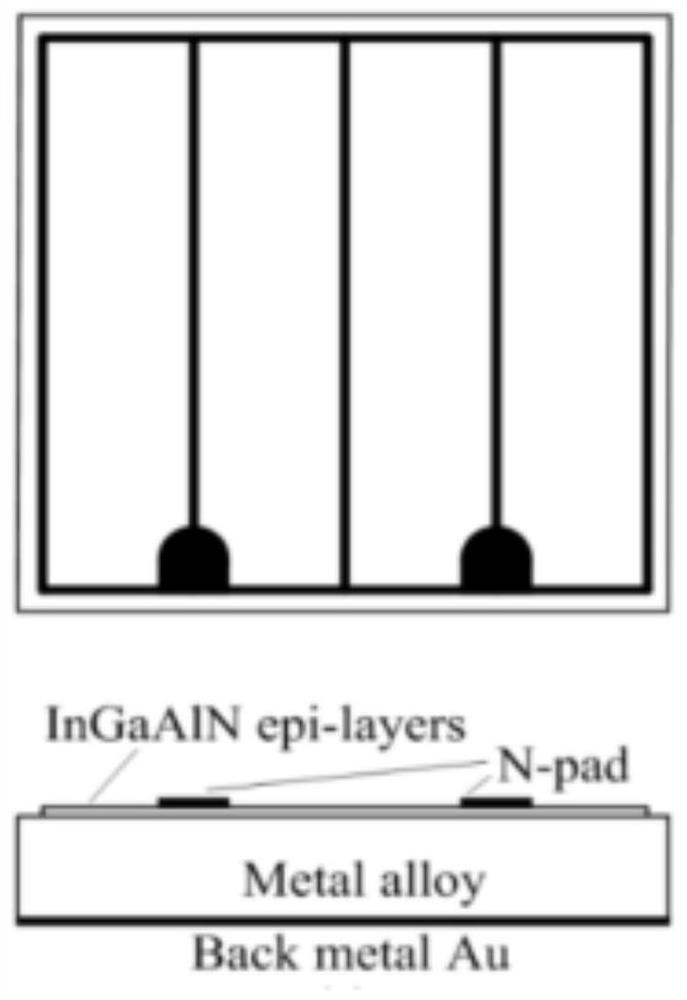
[0058] This embodiment provides a vertically mounted integrated unit diode chip, such as Figure 6 As shown, the first conductivity type layer 5, the second conductivity type layer 3, the quantum well active region 4 located on the first conductivity type layer, the second conductivity type electrode 1, the insulating medium layer 2, wherein the first conductivity type The type layer is a p-GaN layer, the second conductivity type layer is an n-GaN layer, and the second conductivity type electrode is an n electrode. The trench depth Lx between the diode cells is half the thickness L of the n-GaN layer.

Embodiment 3

[0060] This embodiment provides a vertically mounted integrated unit diode chip, such as Figure 7 As shown, the diode mesa structure includes 4 rows of a total of 30 ladder-shaped diode units of equal size and uniform distribution, and the length of the diode unit along the x-axis direction is 40 microns. The size of the mesa structure is smaller than the diffusion length of the current injection. The shape of the diode units is trapezoidal and distributed according to a uniform symmetrical arrangement. The angle between the side wall of the diode unit and the horizontal plane is greater than 0 degrees and less than or equal to 90 degrees 90, and the shape of the side wall of the diode unit is trapezoidal.

[0061] Such as Figure 8 As shown, the diode cell has a sidewall surface with grooves distributed from the bottom to the top of the mesa. The cross-sectional shape of the trench on the side wall of the diode unit is triangular, the width of the trench on the side wall ...


PUM

PropertyMeasurementUnit
Lengthaaaaaaaaaa
Widthaaaaaaaaaa
Thicknessaaaaaaaaaa

Abstract

The invention provides a vertical integrated unit light-emitting diode, which comprises a first conductive type electrode, a second conductive type electrode and a diode mesa structure located on thefirst conductive type electrode, wherein the diode mesa structure comprises n diode units and a trench structure, and n is greater than or equal to 2; the trench structure is located between the diodeunits. The diode mesa structure further comprises a first conductive type layer, a second conductive type layer and a quantum well active region located on the first conductive type layer, wherein the depth of the trench structure is less than or equal to the thickness of the second conductive type layer, and the area of the mesa structure is determined according to the current diffusion length.The technical problem that a diode structure in the prior art is greatly limited in three important parameters, namely, the lumen efficiency, the lumen density output and the lumen cost, is solved, the lumen output of a unit area chip is improved, and the lumen cost is reduced.

Description

technical field [0001] The invention relates to the field of semiconductor materials and device technology, in particular to semiconductor optoelectronic devices. Background technique [0002] In conventional vertical structure LED chips, the current diffusion mainly depends on the n-electrode side, and there are electrode lead-type leads or drill-type leads, but the overall current diffusion is still uneven, resulting in loss of luminous efficiency and uneven heat dissipation, thus affecting the unit. Efficiency and stability of diode chips. This restricts vertical high-power LED chips from providing products with higher lumen output per unit area. Uneven current diffusion, uneven thermal diffusion, and uneven light extraction lead to great limitations in the three important parameters of lumen efficiency, lumen density output, and lumen cost. The vertical LED chip technology currently on the market An effective solution cannot be provided. [0003] The prior art one is ...

Claims


Application Information

Patent Timeline
IPC IPC(8): H01L27/02H01L29/861
CPCH01L27/0207H01L27/0203H01L29/8613
Inventor 闫春辉蒋振宇
Owner 纳微朗科技(深圳)有限公司
Why Eureka
Try Eureka