E*B probe

A probe and ion filtering technology, applied in the field of ion measurement, which can solve the problems of limited application space, uneven distribution of magnetic field edges, and increased ion number.

Active Publication Date: 2020-10-30
SHANGHAI JIAO TONG UNIV +1
View PDF11 Cites 3 Cited by
  • Summary
  • Abstract
  • Description
  • Claims
  • Application Information

AI Technical Summary

Problems solved by technology

The traditional E×B probe can measure better results in the small angle range of the plume center, and a large amount of impurities will affect the measurement results if the angle deviates slightly from the plume centerline. Therefore, the E×B probe is usually used to measure the average Measured near the center of the plume
At the same time, because the number of ions finally received by E×B probes is too small, some E×B probes increase the number of ions that can be collected at the cost of reducing the probe resolution.
The traditional E×B probe uses a permanent magnet with strong magnetism to provide a fixed magnetic field, which has the problem that the magnetic field distribution is not uniform and makes it difficult to measure. Although the method of using an electromagnet instead of a permanent magnet can make the magnetic field relatively stable and controllable, However, the space required to achieve the same field strength level as that of permanent magnets is too large, which limits its application space
[0005] To sum up, the traditional E×B probe has the following points to be improved: (1) The entrance collimation cylinder structure is adopted, and the range of plume receiving by the short entrance collimation cylinder is too large. There are too many impurities; the number of ions received by the long-entrance collimation cylinder is too small, and accurate detection results cannot be obtained
(2) The permanent magnet device is used, and the uneven distribution of the magnetic field edge is not easy to measure
The E×B probe has uneven magnetic field distribution, and there are a lot of impurities that affect the measurement results

Method used


Image

  • E*B probe
  • E*B probe
  • E*B probe

Examples


Embodiment Construction

[0041]The present invention will be described in detail below in conjunction with specific embodiments. The following examples will help those skilled in the art to further understand the present invention, but do not limit the present invention in any form. It should be noted that those skilled in the art can make several changes and improvements without departing from the concept of the present invention. These all belong to the protection scope of the present invention.

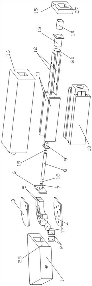
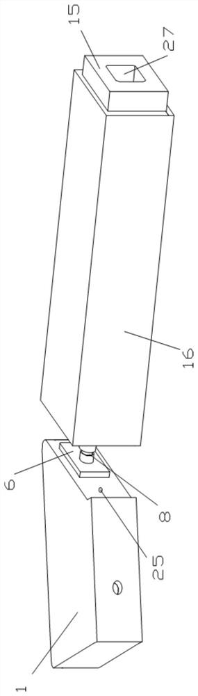
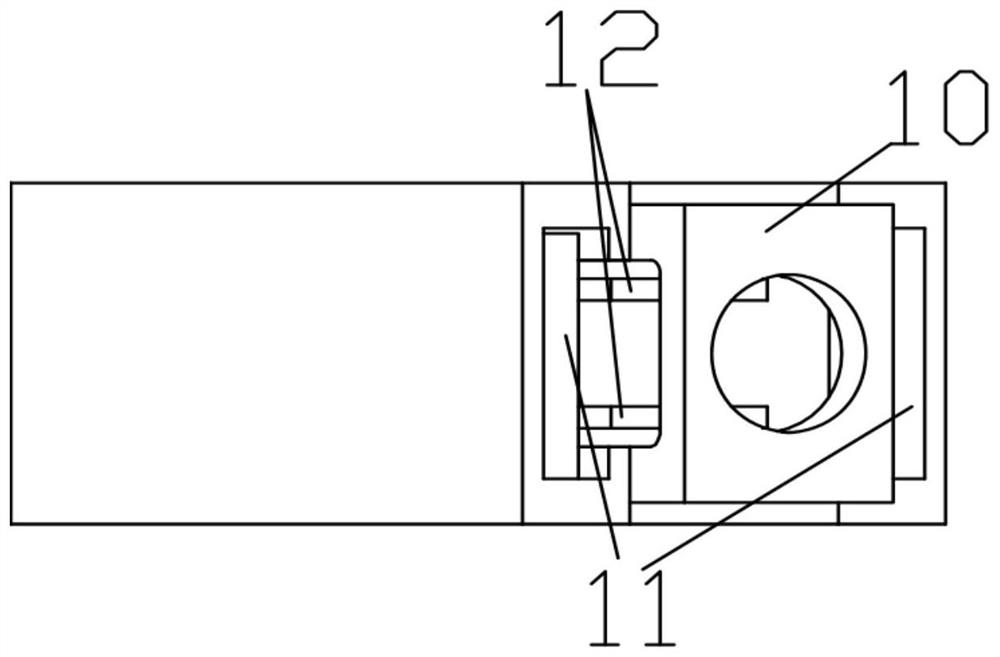
[0042] The E×B probe of the present invention is based on the basic structure of velocity filtering, and the particles with a certain velocity are screened out through an orthogonal electromagnetic field. The demand for plume detection has strict requirements on the accuracy of the E×B probe. For plume detection, only ions with the same effective accelerating voltage can be separated from ions with different valence states after the speed selection of the E×B probe. In the plasma detection of the present...


PUM


Abstract

The invention provides an E * B probe. The E * B probe comprises an ion filtering and collimating module, a connecting piece, a collimating cylinder and an E * B speed filtering module, the ion filtering and collimating module comprises an ion filtering device shell, an ion filtering inlet collimating device, an insulating plate cover, an insulating plate and an arc-shaped electrode, the insulating plate is fixed in the middle of the ion filtering device shell, the arc-shaped electrode is tightly attached to the insulating plate, and the insulating plate cover is arranged on the arc-shaped electrode; the ion filtering inlet collimating device is arranged at an ion filtering inlet of the ion filtering device shell; the connecting piece is fixed at an ion filtering outlet of the ion filtering device shell, the front end of the collimation cylinder penetrates through the connecting piece and extends into the ion filtering device shell to be close to the arc-shaped electrode, and the rearend of the collimation cylinder is arranged in the E * B speed filtering module. According to the E * B probe, the arc-shaped electrode, the collimation magnetic screen and the outlet collimation magnetic screen are adopted, so that the resolution ratio of the E * B probe is improved, and the impurity content in a result is reduced.

Description

technical field [0001] The invention relates to the technical field of plasma measurement, in particular to a novel E×B probe, especially a high-precision E×B probe, which is used for measuring ion distribution and application in plasma. Background technique [0002] Space missions are high-risk, high-difficulty, and high-cost activities. The pursuit of low cost and high efficiency promotes the vigorous development of space propulsion systems. In chemical propulsion with relatively mature technology, solid propulsion has the advantage of large thrust, but it cannot be started multiple times; in liquid propulsion, bicomponent liquid propulsion can generate high specific impulse, but the technology is complex and expensive. The current near-Earth space missions and deep space exploration missions put forward higher requirements on the space propulsion system. Electric propulsion is a propulsion technology that utilizes electric energy to ionize and accelerate working fluid in...

Claims


Application Information

Patent Timeline
Patent Type & Authority Applications(China)
IPC IPC(8): H05H1/00
CPCH05H1/0081
Inventor 王平阳余盛楠杭观荣刘佳贾晴晴田雷超
Owner SHANGHAI JIAO TONG UNIV
Why Eureka
Try Eureka