Case temperature control device

A temperature control device and chassis technology, which is applied in the direction of using gaseous coolant for modification, cooling/ventilation/heating transformation, electrical components, etc., can solve the problem of inability to measure the external temperature, affect the operation of the whole station, and cannot effectively monitor the operating status of the chassis fan And other issues

Pending Publication Date: 2020-10-30
国网河南省电力公司超高压公司 +1
View PDF10 Cites 1 Cited by
  • Summary
  • Abstract
  • Description
  • Claims
  • Application Information

AI Technical Summary

Problems solved by technology

[0003] 1. The temperature control of the chassis is simple, relying on the cooling fan in the radiator on the front panel of the chassis to dissipate heat from the chassis. The fan runs continuously without control and cannot adjust the speed according to the temperature in the chassis. The fan runs at high speed for a long time and is easy to be damaged. Once damaged, it must be replaced in time, resulting in a large maintenance workload for the control and maintenance host;
[0004] 2. It is impossible to effectively monitor the temperature of the chassis and the operating status of the fan. Once the fan is damaged and out of operation, the temperature of the chassis will be too high, which will cause the host system to fail and affect the operation of the whole station. Major anti-accident measures" 8.5.3.1 Requirements on "monitoring the operating temperature of the main b

Method used


Image

  • Case temperature control device
  • Case temperature control device
  • Case temperature control device

Examples


Embodiment 1

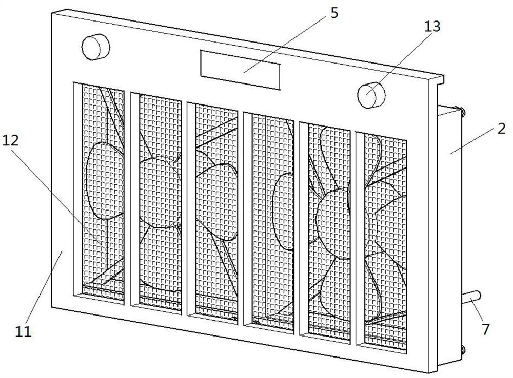
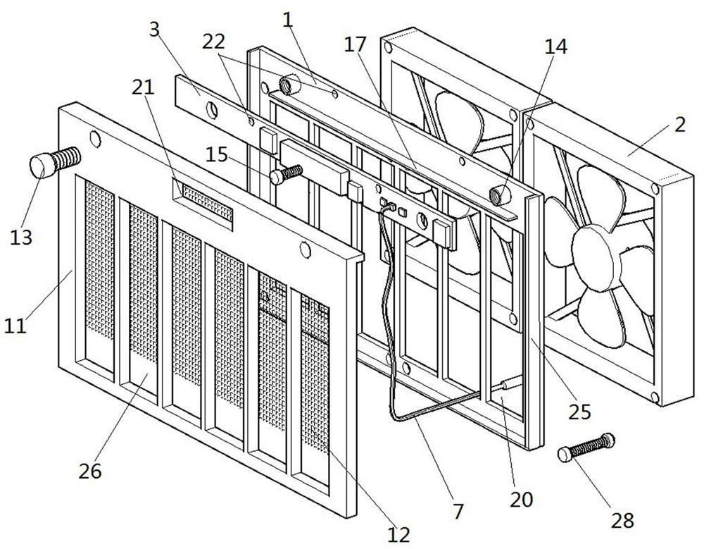
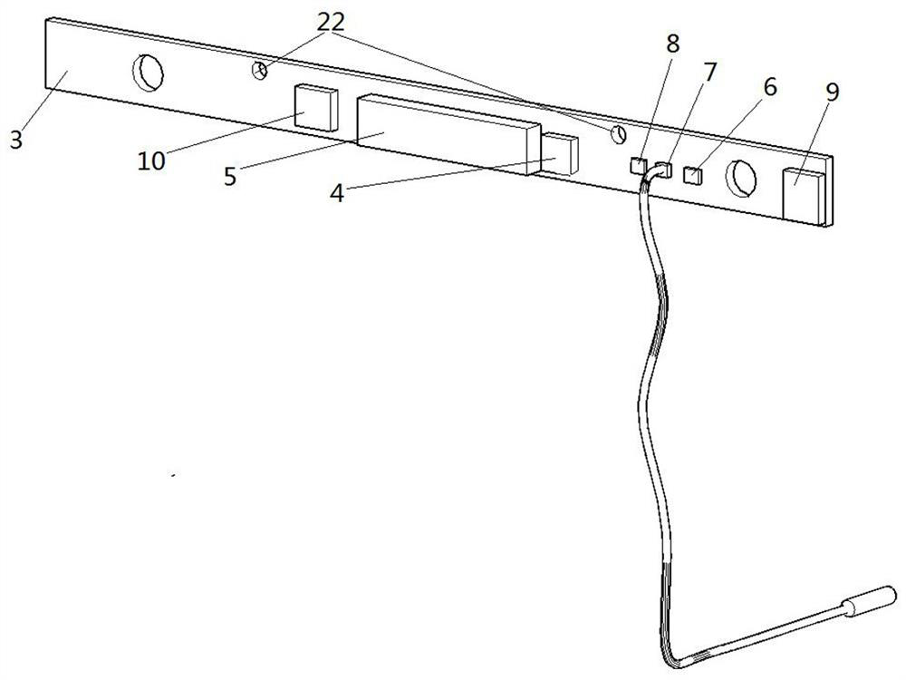
[0033] Such as Figure 1-3 Shown is the first embodiment of the present invention, a chassis temperature control device, including a fixed frame 1, the fixed frame 1 is a cuboid plastic plate made of epoxy resin, the lower part of the fixed frame 1 is hollowed out, and is uniformly cut by a cutting machine Out of multiple through holes a 20, such as figure 1 and figure 2 As shown, two exhaust fans 2 are installed on the lower part of the rear of the fixed frame 1 through bolts 228. The model of the exhaust fan 2 is FD128025EB-N, and the upper part of the front of the fixed frame 1 is not hollowed out. image 3As shown, a central processing unit 4 is set on the circuit board 3, the central processing unit 4 is an MPU, the model is STM32F103C8T6, a power supply module 10 is set on the circuit board 3, a display 5, a temperature sensor 2 7, a real-time clock 8 and a TF card 9 are also set , the model of display 5 is DIG2841BS, the model of temperature sensor 1 6 is DS18B20, th...

Embodiment 3

[0038] Such as Figure 5 Shown is the third embodiment of the present invention. The difference between this embodiment and the first embodiment is that a differential pressure switch 18 is mounted on the horizontal plate 17 through screws, an indicator light 19 is mounted on the circuit board 2, and the power module 10 is The switch 18 is electrically connected with the indicator light 19. When the pressure difference on both sides of the filter screen 12 reaches a certain value, the pressure difference switch 18 is closed, and the indicator light 19 is on, indicating that the filter screen 12 is full and needs to be replaced. Machine punches the through hole five 24 that matches with indicator lamp 19.

Embodiment 4

[0040] Such as Figure 6 Shown is the fourth embodiment of the present invention, the difference between this embodiment and the first embodiment is that the clock backup battery 27 provides backup power for the real-time clock 8, the model of the clock backup battery 27 is CR1220, and the clock backup battery 27 is set at on circuit board 3.


PUM


Abstract

The invention discloses a case temperature control device. The device comprises a fixing frame, wherein one side of the fixing frame is provided with an exhaust fan, the other side of the fixing frameis provided with a circuit board, the circuit board is provided with a central processing unit, a display, a temperature sensor I, a temperature sensor II, a real-time clock, a TF card and a power supply module for supplying power to the central processing unit; a motor of the exhaust fan, the display, the temperature sensor I, the temperature sensor II, the real-time clock and the TF card are electrically connected with the central processing unit; a movable plate is arranged on the other side of the fixing frame; a through hole II matched with the display is formed in the movable plate; a cavity is formed between the movable plate and the fixing frame; and a filter screen is arranged in the cavity. According to the invention, the rotating speed of the exhaust fan can be adjusted according to the temperature difference between the interior and the exterior of the case, and energy is saved; the temperature of the case and the running state of the fan are effectively monitored, the time when the temperature exceeds the limit value, the temperature data inside and outside the case and the rotating speed of the exhaust fan are recorded in the TF card, and post-analysis is facilitated.

Description

technical field [0001] The invention relates to the field of temperature control of industrial control cabinets, in particular to a cabinet temperature control device. Background technique [0002] In the substation, there are defects in the design of the temperature controller of the control and protection host chassis, which are mainly manifested in the following three aspects: [0003] 1. The temperature control of the chassis is simple, relying on the cooling fan in the radiator on the front panel of the chassis to dissipate heat from the chassis. The fan runs continuously without control and cannot adjust the speed according to the temperature in the chassis. The fan runs at high speed for a long time and is easy to be damaged. Once damaged, it must be replaced in time, resulting in a large maintenance workload for the control and maintenance host; [0004] 2. It is impossible to effectively monitor the temperature of the chassis and the operating status of the fan. On...

Claims


Application Information

Patent Timeline
IPC IPC(8): H05K7/20
CPCH05K7/20209H05K7/20136
Inventor 连进灿陈炳华聂晶王宇婕申磊荆扬陈晓王晓鹏王海龙潘钰
Owner 国网河南省电力公司超高压公司
Why Eureka
Try Eureka