Rotary tool for double-sided friction stir welding, double-sided friction stir welding device, and double-sided friction stir welding method

A rotary tool and friction stir technology, applied in the field of rotary tools for double-sided friction stir welding, can solve problems such as undocumented, inability to obtain joints, and no consideration of metal plate joining, etc.

Active Publication Date: 2020-10-30
JFE STEEL CORP
View PDF13 Cites 1 Cited by
  • Summary
  • Abstract
  • Description
  • Claims
  • Application Information

AI Technical Summary

Problems solved by technology

[0025] However, the techniques disclosed in Patent Documents 6 and 7 are aimed at reinforcement of welded parts or surface hardening of metals, and application to the joining of metal plates is not considered at all.
The tips of the rotary tools disclosed in these techniques are described as being flat or planar, but there is no description of forming a concave or convex curved surface for the purpose of improving plastic flow.
In addition, the conventional rotary tools described in the above-mentioned Patent Documents 6 and 7 are not described as having a spiral step portion formed in a direction opposite to the rotation direction.
Therefore, when the above-mentioned conventional rotary tool is used for joining metal plates, sufficient plastic flow cannot be obtained in the thickness direction of the plates, and there is a possibility of poor joining.
[0026] In addition, although the technologies disclosed in Patent Documents 8 to 11 are aimed at joining metal plates by the friction stir method, application to the double-sided friction stir welding method is not considered at all.
That is, Patent Documents 8 to 11 do not disclose an appropriate relationship between the diameter of the tool end portion and the thickness of the metal plates to be joined in the double-sided friction stir welding method, so there is a possibility that a sound joint cannot be obtained.

Method used


Image

  • Rotary tool for double-sided friction stir welding, double-sided friction stir welding device, and double-sided friction stir welding method
  • Rotary tool for double-sided friction stir welding, double-sided friction stir welding device, and double-sided friction stir welding method
  • Rotary tool for double-sided friction stir welding, double-sided friction stir welding device, and double-sided friction stir welding method

Examples


no. 1 Embodiment approach

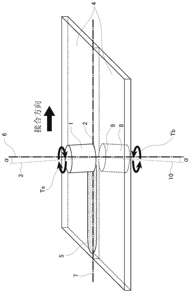
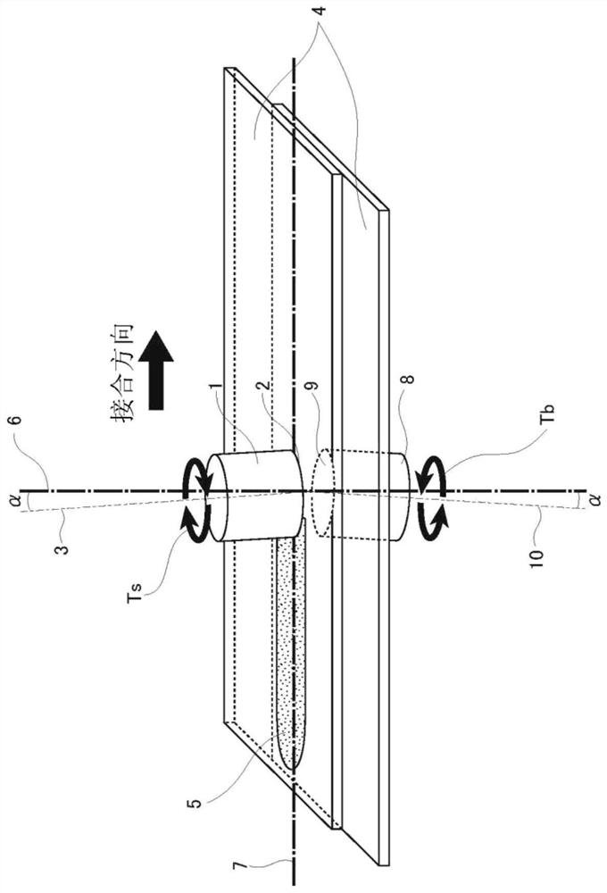
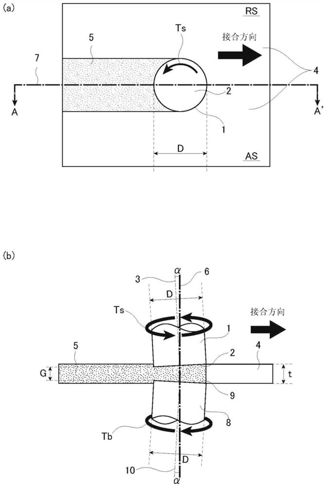
[0089] like Figure 5 (a) and Figure 5 As shown in (b), the rotary tools 1 and 8 of the present invention according to the first embodiment are constituted only by the end portion 11 whose round end is formed into a planar shape 11a. In the planar tip portion 11 , the tip surface that contacts the metal plate is constituted by one plane perpendicular to the rotation axes of the rotary tools 1 , 8 . Unlike conventional rotary tools, this end face does not have a probe protruding toward the metal plate. In addition, if Figure 5 As shown in (b), the rotary tools 1 and 8 can be provided with one or more spiral (helical) steps 12 in the direction opposite to the above-mentioned rotation direction at the tip portion 11 . In addition, the above-described step portion 12 b or groove portion 12 c is provided on the step portion 12 .

no. 2 Embodiment approach

[0091] like Image 6 (a) and Image 6 As shown in (b), the rotary tools 1 and 8 according to the second embodiment are composed only of the tip portion 11 having a rounded tip and a convex curved surface 11b, and the tip of the rotary tool protrudes. The conventional rotary tool has a probe that protrudes toward the metal plate, and the shoulder and the probe are in a discontinuous shape, while the convex curved end portion 11 has a continuous shape without the probe and forms an approximately same slope. In other words, in the convex curved terminal portion 1, the terminal surface in contact with the metal plate is constituted by a curved surface (paraboloid, ellipsoid, or spherical surface) protruding toward the center direction, and includes rotation in the vertical direction relative to the metal plate. In the cross-sectional shape of the axis, it is a curve with substantially the same radius of curvature. In addition, if Image 6 As shown in (b), the rotary tools 1 an...

no. 3 Embodiment approach

[0096] like Figure 7 (a) and Figure 7 As shown in (b), the rotary tools 1 and 8 according to the third embodiment are constituted only by the tip portion 11 having a rounded tip and a concave curved surface 11c, and the tip of the rotary tool is recessed. The conventional rotary tool has a probe that protrudes toward the metal plate, and has a discontinuous shape at the shoulder and the probe, while the concave curved end portion 11 has a continuous shape without the probe, and has approximately the same shape. inclined surface. In other words, in the concave curved end portion 1, the end surface in contact with the metal plate is composed of a curved surface (paraboloid, ellipsoid, or spherical surface) that is concave toward the center direction, and includes the rotation axis in the vertical direction relative to the metal plate. In the cross-sectional shape, it is a curve with approximately the same radius of curvature. Additionally, if Figure 7 As shown in (b), the...


PUM

PropertyMeasurementUnit
tensile strengthaaaaaaaaaa
Vickers hardnessaaaaaaaaaa

Abstract

The present invention addresses the problem of providing: a rotary tool for double-sided friction stir welding in which two metal plates are welded while a pair of rotary tools facing each other are rotated in opposite directions; a double-sided friction stir welding device using the rotary tool for double-sided friction stir welding; and a double-sided friction stir welding method. A rotary toolwhich is for double-sided friction stir welding and is used for double-sided friction stir welding, in which a pair of rotary tools disposed on unwelded surfaces of one metal plate and another metal plate, respectively, are rotated in opposite directions to weld the metal plates, has a distal end section formed in a circular and planar shape, and the distal end section is formed of a more rigid material than the metal plate.

Description

technical field [0001] The present invention relates to a rotary tool for double-sided friction stir welding for double-sided friction stir welding for joining two metal plates while rotating a pair of opposing rotary tools in opposite directions, and to using the rotary tool for double-sided friction stir welding A double-sided friction stir welding device of a rotary tool and a double-sided friction stir welding method. Background technique [0002] Patent Document 1 discloses that both or one of a pair of metal plates are rotated to soften the metal plates by generating frictional heat, and the softened parts are stirred to generate plastic flow. Sheet metal joins this technique. [0003] However, the technology described in this patent document 1 needs to rotate members such as metal plates to be joined, so there are limitations in the shape and size of members such as metal plates to be joined. [0004] On the other hand, as a friction welding method different from Pa...

Claims


Application Information

Patent Timeline
Patent Type & Authority Applications(China)
IPC IPC(8): B23K20/12
CPCB23K20/1255B23K20/125B23K20/123B23K20/1225
Inventor 松下宗生池田伦正松田广志山岸大起
Owner JFE STEEL CORP
Why Eureka
Try Eureka