Connecting structure for assembly type concrete shear wall edge member

A technology for concrete shear walls and edge components, which is applied to building components, building structures, walls, etc., can solve the problem of low shear resistance of horizontal joints, improve anchorage performance, ensure ductility performance, and improve compressive deformation capacity. Effect

Inactive Publication Date: 2012-09-26
SOUTHEAST UNIV
View PDF9 Cites 17 Cited by
  • Summary
  • Abstract
  • Description
  • Claims
  • Application Information

AI Technical Summary

Problems solved by technology

[0004] The known connection structure mainly solves the connection problem of the vertical reinforcement through the grout-anchor lap connection or the grout-anchor sleeve connection, while the traditional cast-in-place design structure is still adopted for concrete constraints such as hoop ratio and horizontal reinforcement. This structure is sufficient for the cast-in-situ structure with continuous vertical reinforcement, but the vertical reinforcement of the prefabricated concrete shear wall is disconnected at this position, and the overlapping or anchoring of the vertical reinforcement in this position will make the concrete ( or grouting material) in a more complex stress state; the joints of the upper and lower edge components also adopt the dry joint connection method of cement mortar sitting grout, and the shear resistance of the horizontal joints is not high

Method used


Image

  • Connecting structure for assembly type concrete shear wall edge member
  • Connecting structure for assembly type concrete shear wall edge member
  • Connecting structure for assembly type concrete shear wall edge member

Examples


Embodiment Construction

[0017] The present invention will be further described below in conjunction with accompanying drawing and specific embodiment:

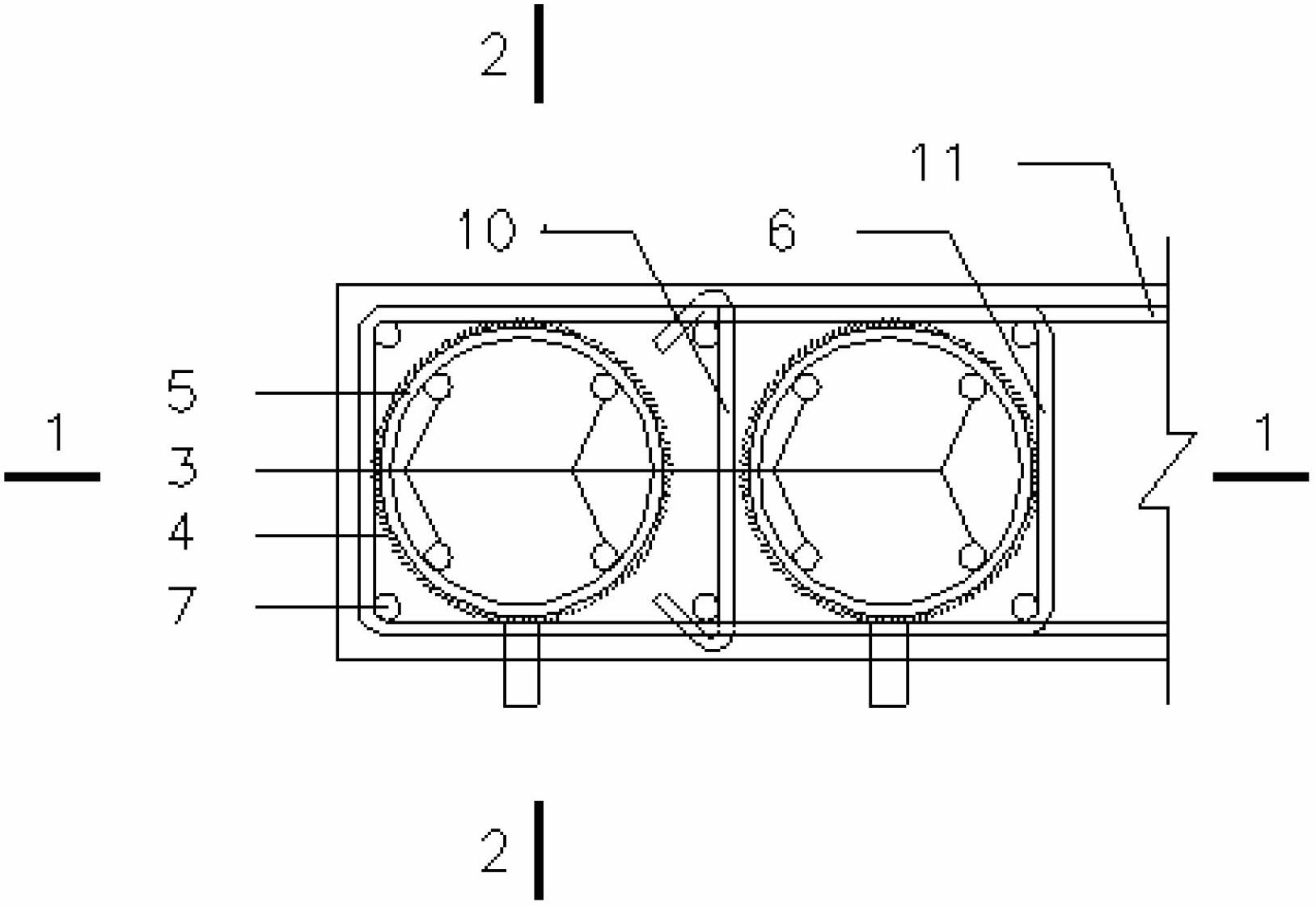
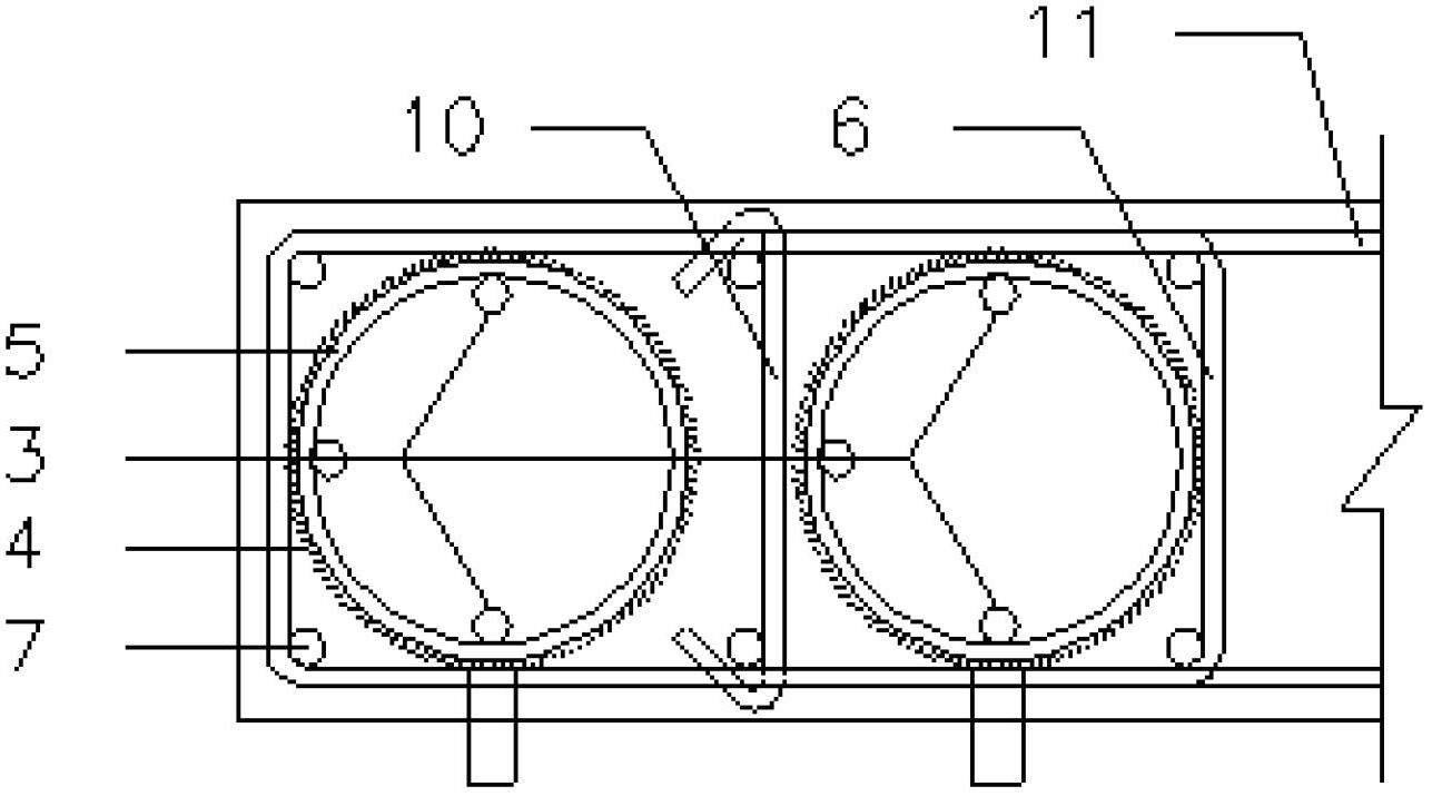
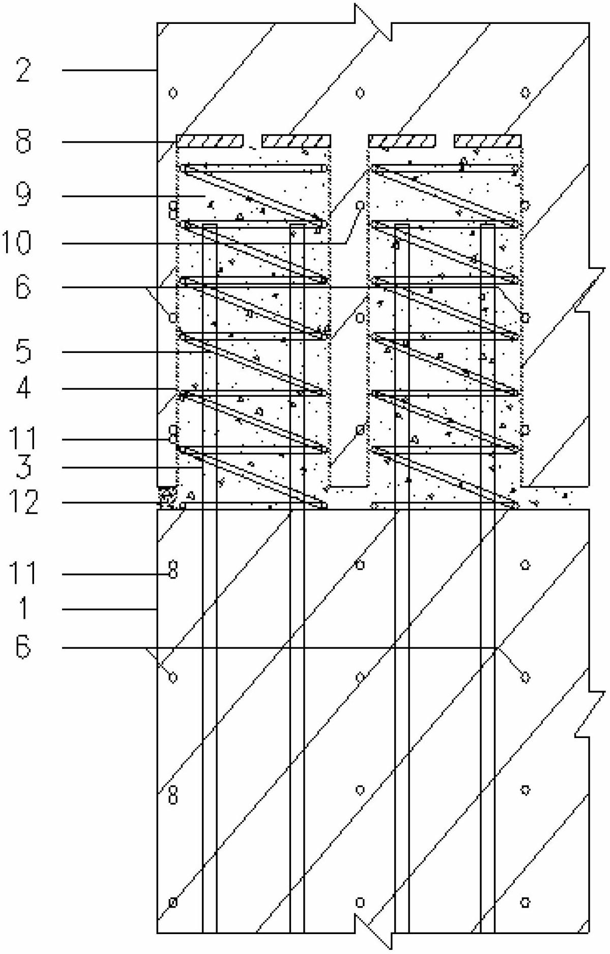
[0018] Such as figure 1 , 2 , 3 and 4 show: a kind of prefabricated concrete shear wall edge member connection structure, the edge member 1 of the prefabricated shear wall panel on the lower floor except the designed stirrup 6, the designed vertical steel bar 7, the horizontal hook head tie bar 10, and the horizontal steel bar 11, a certain length of vertical connecting reinforcement 3 is reserved; the edge member 2 of the prefabricated shear wall panel on the upper floor, except for the designed stirrup 6, the designed vertical reinforcement 7, the horizontal hook head tie bar 10, and the horizontal Pre-buried the large-diameter metal bellows 4 to form holes, and set the end plugging plate 8, the feed port 13 and the discharge port 14; figure 1 It is a schematic diagram of four vertically connected steel bars 3 inside a large-diameter metal bellow...


PUM


Abstract

The invention discloses a connecting structure for an assembly type concrete shear wall edge member. vertical connecting reinforcing steel bar, which can be provided with an upset head, is reserved through a hole reserved in a large-diameter metal bellows, and is sleeved with a continuous spiral stirrup; then the vertical connecting reinforcing steel bar and the continuous spiral stirrup are commonly inserted into the large-diameter metal bellows; and fine aggregate concrete (or a grounding material) is poured into the metal bellows, so that the reliable connection of the edge member is realized. Due to reliable anchoring of the vertical connecting reinforcing steel bar, the optimization of the diameter, the quantity and the plane arrangement of the vertical connecting reinforcing steel bar, and the increase of the wet joint area on a splicing surface, full exertion of the bearing capacity of the shear wall is ensured; and multiple effective restrain for the subsequentlly-poured fine aggregate concrete (or the grouting material) is formed by the shear wall stirrup, a horizontal tie bar, the metal bellows and the continuous circular spiral stirrup, and thus the integral performance of the part is remarkably improved. According to the connecting method for the edge member, which is provided by the invention, the stress continuousness of the vertical steel reinforcing bar is ensured, the deformaility and the ductility performance of the vertical steel reinforcing bar are remarkably improved, and the shock resistance of the assembly type concrete shear wall is improved. Meanwhile, the method is simple in manufacturing process and facilitates the practice and application.

Description

technical field [0001] The invention relates to an edge member of a prefabricated concrete shear wall, which adopts a large-diameter metal corrugated circular tube hole and a steel bar lap connection structure in the hole, and belongs to the technical field of prefabricated concrete shear wall structures in construction engineering. Background technique [0002] The edge members of the shear wall are generally arranged in more important structural parts with greater stress, and the requirements for the ratio of vertical reinforcement and the characteristic value of hoops are more stringent. Therefore, the bearing capacity, deformation capacity and ductility of the edge members are important factors to ensure the seismic reliability of the shear wall and even the overall structure. [0003] Prefabricated concrete shear walls are generally prefabricated in layers, and the vertical steel bars and concrete are disconnected at the horizontal joints. In view of the importance of ...

Claims


Application Information

Patent Timeline
Patent Type & Authority Applications(China)
IPC IPC(8): E04B2/56
Inventor 刘家彬郭正兴朱张峰
Owner SOUTHEAST UNIV
Why Eureka
Try Eureka