Rotary nursery stock pruning device
A pruning device and rotary technology, applied in cutting tools, cutting equipment, gardening, etc., can solve problems such as inconvenient operation, inability to pruning seedlings, and hard work of workers, so as to enhance practicality, enhance aesthetics and appreciation, and expand The effect of scope
- Summary
- Abstract
- Description
- Claims
- Application Information
AI Technical Summary
Problems solved by technology
Method used
Image
Examples
Embodiment 1
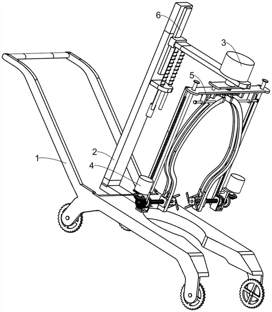
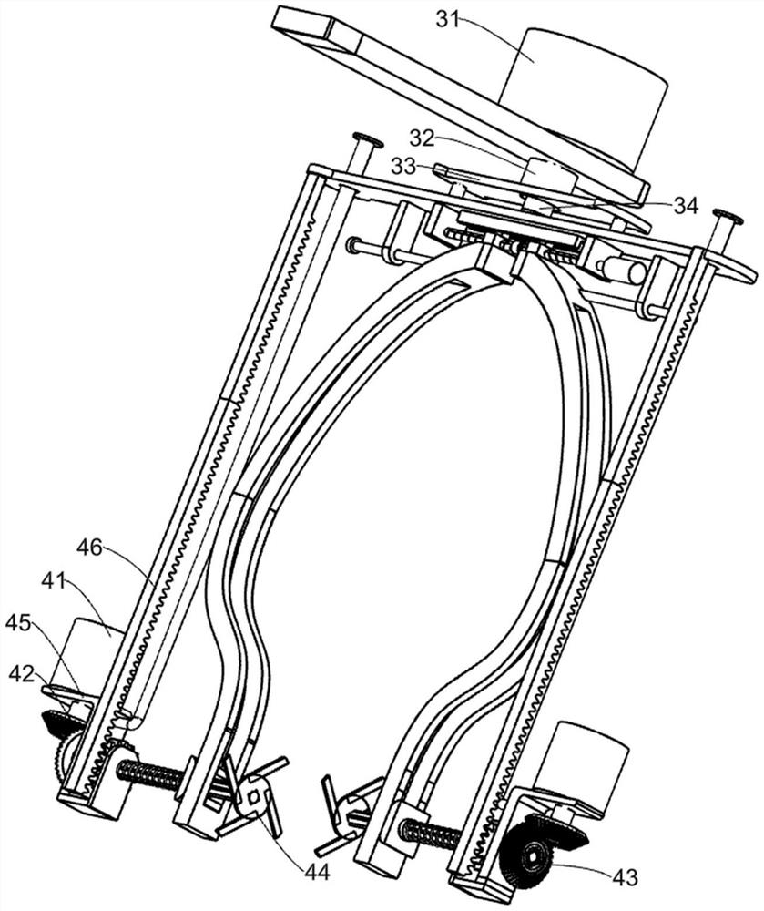
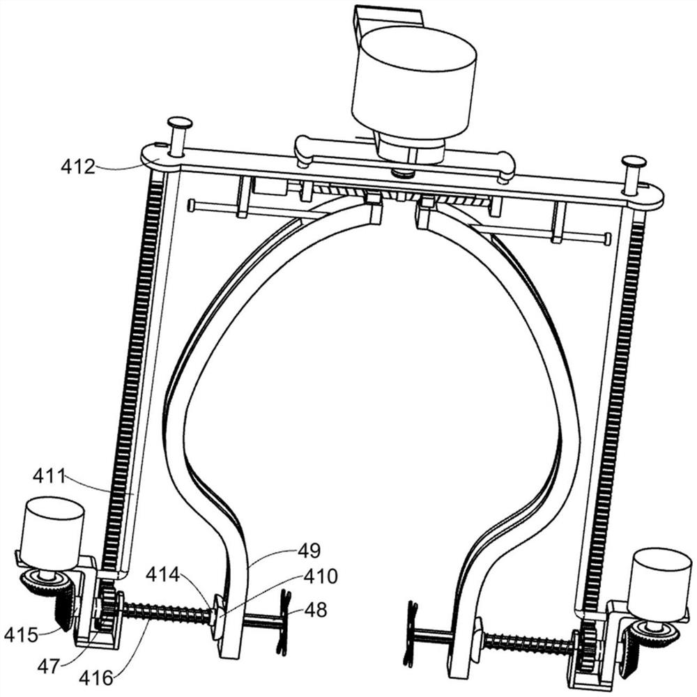
[0024] A rotary pruning device for seedlings, such as Figure 1-6 As shown, it includes a cart frame 1, a support frame 2, a rotating assembly 3, and a trimming assembly 4. The cart frame 1 is provided with a circular hole, and the support frame 2 is fixed on one side of the cart frame 1. The rotating assembly 3 is arranged on the support frame 2. The rotating assembly 3 includes a rotating motor 31, a hollow movable shaft 32, a support plate 33, a connecting shaft 34 and a connecting plate 63, and the connecting plate 63 is arranged on the upper part of the support frame 2. On one side of the rotating motor 31, the rotating electric machine 31 is fixedly arranged on the connecting plate 63, the hollow movable shaft 32 is rotatably arranged on the connecting plate 63, and the connecting shaft 34 is fixedly connected to the output shaft of the rotating electric machine 31 and passes through the hollow The movable shaft 32, the supporting plate 33 is fixedly connected to the hollo...
Embodiment 2
[0028] On the basis of Example 1, such as Figure 3-4 As shown, it also includes a guide block 413, a small bearing 414, a sleeve shaft 415 and a first elastic member 416. The guide rail 49 is arc-shaped and the middle of the guide rail 49 is provided with an arc hole 417, and the arc hole 417 slides There are two guide blocks 413 and one side surface of the sliding block 410 is fixedly connected with the two guide blocks 413. The small bearing 414 is fixed on the sliding block 410. The rotating shaft 48 is a spline shaft and is connected to the small bearing 414. The inner ring is fixedly connected, the sleeve shaft 415 is arranged on the fixed plate 45 through a bearing, and the rotating shaft 48 is slidably located in the sleeve shaft 415. The second bevel gear 43 and the rotating gear 47 are respectively fixed on two sides of the sleeve shaft 415. At the end, a first elastic member 416 is provided between the fixed plate 45 and the small bearing 414 and the rotating shaft 4...
Embodiment 3
[0031] On the basis of Example 2, such as figure 1 with Figure 5 As shown, it also includes a width adjustment assembly 5 for adjusting the distance between the two trimming blades 44 and the two guide rails 49. The width adjustment assembly 5 is provided on the horizontal plate 412. The width adjustment assembly 5 includes a two-way screw. 51. The horizontal guide rod 52, the horizontal slide rail 53, the horizontal sliding block 54, the moving nut 55, the square mounting block 56 and the strip mounting block 57, the bottom side of the horizontal plate 412 is fixed with two symmetrical square mounting blocks 56, The two-way screw 51 is rotatably arranged in two square mounting blocks 56. The two-way screw 51 is provided with two moving nuts 55 and the upper sides of the two guide rails 49 are respectively fixedly connected to the bottom sides of the two moving nuts 55. The screw 51 and the two moving nuts 55 work together to adjust the distance between the two guide rails 49. ...
PUM
 Abstract
Description
Claims
Application Information
 - R&D
- Intellectual Property
- Life Sciences
- Materials
- Tech Scout
- Unparalleled Data Quality
- Higher Quality Content
- 60% Fewer Hallucinations
Browse by: Latest US Patents, China's latest patents, Technical Efficacy Thesaurus, Application Domain, Technology Topic, Popular Technical Reports.
© 2025 PatSnap. All rights reserved.Legal|Privacy policy|Modern Slavery Act Transparency Statement|Sitemap|About US| Contact US: help@patsnap.com


