
Steering conveying rail and automatic grinding production line

A conveying track and production line technology, which is applied in the field of grinding processing, can solve the problems of single-sided grinding of workpieces to be ground, slow production speed, complex structure, etc., and achieves the effects of simple structure, increased output ratio, and improved production efficiency.

Pending Publication Date: 2020-11-03
SHANGQIU STAR GRP ELECTRONICS IND
View PDF0 Cites 0 Cited by
  • Summary
  • Abstract
  • Description
  • Claims
  • Application Information

AI Technical Summary

Problems solved by technology

During the grinding process of the end face of the workpiece to be ground, there are problems such as fragility, breakage, and corrosion. Especially in the process of grinding the upper end face of the workpiece to be ground for tile shape, two surface grinders are generally used to grind the inner arc and the outer arc respectively. The product is clamped on the workbench of the grinding machine. The workbench reciprocates in the X direction. The Y-axis is equipped with a special gold-steel grinding wheel. The product is ground by the rotation of the grinding wheel. The Y-axis is manually controlled to feed downward (single feed 0.03mm), grinding 4 products at a time, and the grinding output is 60 pieces / H. This grinding method requires extremely high technical proficiency of workers, and the production speed is slow and the efficiency is low.
[0003] After the upper end surface of the workpiece to be ground is ground, it needs to be turned over to grind the lower end surface. Manual overturning is not only inefficient, but also easily causes damage to the workpiece. The existing automatic steering device is not only complex in structure, but also requires precise positioning control. , and the cost is higher
In addition, the common processing method of the existing side grinding device is to use a double-end surface grinding machine, and use the high-speed rotating grinding wheel at both ends of the grinding machine to process the two ends of the workpiece to be ground, which cannot meet the demand for single-side grinding of the workpiece to be ground.

Method used


Image

  • Steering conveying rail and automatic grinding production line
  • Steering conveying rail and automatic grinding production line
  • Steering conveying rail and automatic grinding production line

Examples


Embodiment 1

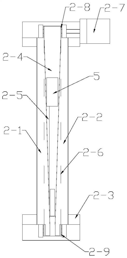
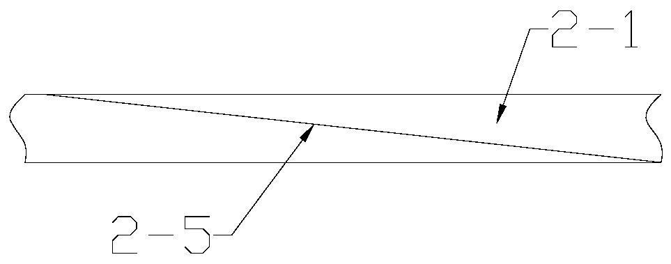
[0031] Such as figure 1 with 2 As shown, a steering conveyor track includes a first limit baffle 2-1 and a second limit baffle 2-2 arranged at intervals, and the first limit baffle 2-1 and the second limit baffle 2 Both ends of -2 are fixed on the support base 2-3. Between the first limiting baffle 2-1 and the second limiting baffle 2-2, a workpiece transmission channel 2-4 is formed, and the first limiting baffle 2-1 and the second limiting baffle 2-2 The inner walls are gradually inclined inward along the conveying direction of the workpiece 5, and the conveying channel 2-4 of the workpiece is gradually narrowed along the conveying direction of the workpiece 5. Only allow a single workpiece 5 to pass through vertically. The inner sidewall of the first limit baffle 2-1 is provided with an upwardly inclined turning slope 2-5 along the conveying direction of the workpiece 5, and the turning slope 2-5 starts from the lower end of the first limit baffle 2-1 along the conveying...

Embodiment 2

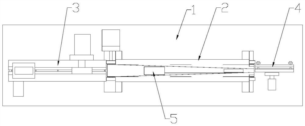
[0035] Such as Figure 3-5 As shown, a kind of automatic grinding production line comprises workbench 1, is installed on the workbench 1 and implements the above-mentioned steering conveying track 2, and the feeding end of diverting conveying track 2 is provided with the first grinding device 3, and the feeding end is provided with There is a second grinding device 4, and the second grinding device 4 includes the first grinding wheel 4-5 and the single-sided grinding guide rail that is positioned at the first grinding wheel 4-5, and the feeding end of the single-sided grinding guide rail is connected to the transfer track The feeding ends of 2 are connected, and the first grinding device 3 includes a machine base 3-1 arranged on the workbench 1. A workpiece conveying mechanism is arranged on the machine base 3-1, and a second grinding machine is arranged above the workpiece conveying mechanism. Wheel 3-10, the feeding end of the workpiece conveying mechanism is provided with f...

Embodiment 3

[0038] This embodiment is basically the same as Embodiment 1, the difference is: as Figure 4 As shown, the workpiece conveying mechanism includes a conveying chain 3-3 arranged on the support 3-1, a driving wheel driven by the first reduction motor 3-2 is installed at one end of the support 3-1, and a driven wheel is installed at the other end. A transmission conveying chain 3-3 is set between the driving wheel and the driven wheel, and a plurality of stoppers 3-5 for pushing the workpiece 5 are fixed at intervals on the conveying chain 3-3, and the distance between adjacent stoppers 3-5 is greater than that of a single The length of the workpiece 5. The upper ends of the frame 3-1 on both sides of the conveyor chain 3-3 are fixed with a slide rail 3-6, the slide rail 3-6 is arranged along the conveying direction of the workpiece 5, and the slide rail 3-6 is close to the side of the conveyor chain 3-3 An L-shaped support groove 3-7 is provided, and the end of the workpiece 5...


PUM


Abstract

The invention provides a steering conveying rail and an automatic grinding production line. The steering conveying rail comprises a first limiting baffle and a second limiting baffle which are arranged in a spaced mode, and a workpiece conveying channel is formed between the first limiting baffle and the second limiting baffle. The inner side walls of the first limiting baffle and the second limiting baffle are both gradually inclined inwards in the workpiece conveying direction, and a steering slope is arranged on the inner side wall of the first limiting baffle in the workpiece conveying direction and obliquely extends upwards from the lower end of the first limiting baffle to the upper end of the first limiting baffle in the workpiece conveying direction; and the workpiece conveying channel is gradually narrowed in the workpiece conveying direction, and a conveying belt for transmission is arranged at the lower end of the workpiece conveying channel. The steering conveying rail is simple in structure, capable of automatically achieving one-by-one steering of workpieces in the horizontal direction and the vertical direction and suitable for assembly line work of the workpieces, the automatic grinding production line achieves automatic and continuous grinding work, and the production efficiency is greatly improved.

Description

technical field [0001] The invention relates to the field of grinding processing, in particular to a steering conveying track and an automatic grinding production line. Background technique [0002] After the rare earth NdFeB raw material is sintered to form a blank, it needs to be ground on multiple surfaces to make it meet the needs of customers. During the grinding process of the end face of the workpiece to be ground, there are problems such as fragility, breakage, and corrosion. Especially in the process of grinding the upper end face of the workpiece to be ground for tile shape, two surface grinders are generally used to grind the inner arc and the outer arc respectively. The product is clamped on the workbench of the grinding machine. The workbench reciprocates in the X direction, and the Y-axis is equipped with a special gold-steel grinding wheel. The product is ground by the rotation of the grinding wheel. The Y-axis is manually controlled to feed downwards (single ...

Claims


Application Information

Patent Timeline
Patent Type & Authority Applications(China)
IPC IPC(8): B24B27/00B24B37/00B24B37/34B24B41/02
CPCB24B27/0023B24B27/0069B24B27/0076B24B37/00B24B37/34B24B37/345B24B41/02
Inventor 郭齐学
Owner SHANGQIU STAR GRP ELECTRONICS IND
Learn More