Supercharge Your Innovation With Domain-Expert AI Agents!

Material collecting yarn guiding device of twisting machine

A twisting machine and wire technology, which is applied in the field of twisting machine receiving wire device, can solve the problems that the yarn receiving quality cannot be guaranteed and cannot be replaced separately, so as to prolong the service life, reduce production costs, and improve applicability Effect

Active Publication Date: 2020-11-03
盐城神威制绳有限公司
View PDF4 Cites 0 Cited by
  • Summary
  • Abstract
  • Description
  • Claims
  • Application Information

AI Technical Summary

Problems solved by technology

In the prior art, when the yarn is taken up, generally the yarn needs to be taken up after being guided by a wire mechanism, but the current wire mechanism is generally similar to the structure disclosed in the patent with the publication number CN208362556U , where the passing coils used for threading are fixed in size. Different yarns and different take-up tensions will produce different forces on the passing coils. Since the passing coils cannot adjust the different tension effects of the yarns, it will cause Different tensions act directly on the take-up reel, and then have different effects on the take-up, and the tension during take-up is directly related to the quality and effect of the take-up of the yarn, so the existing technology of passing the coil cannot Ensure that the quality of the yarn take-up is consistent; in addition, the over-coil is relatively slidingly connected with the yarn for a long time, and the yarn will wear the over-coil, and once the over-coil is damaged, it cannot be replaced separately, and the current over-coil can be detached separately , once it is replaced, it is necessary to adjust the angle of the coil to ensure that the angle of the wire passing through the coil is the same as before the replacement

Method used


Image

  • Material collecting yarn guiding device of twisting machine
  • Material collecting yarn guiding device of twisting machine
  • Material collecting yarn guiding device of twisting machine

Examples


Embodiment Construction

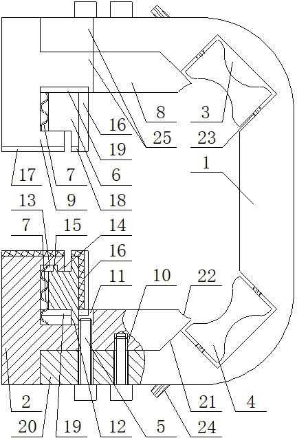
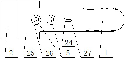
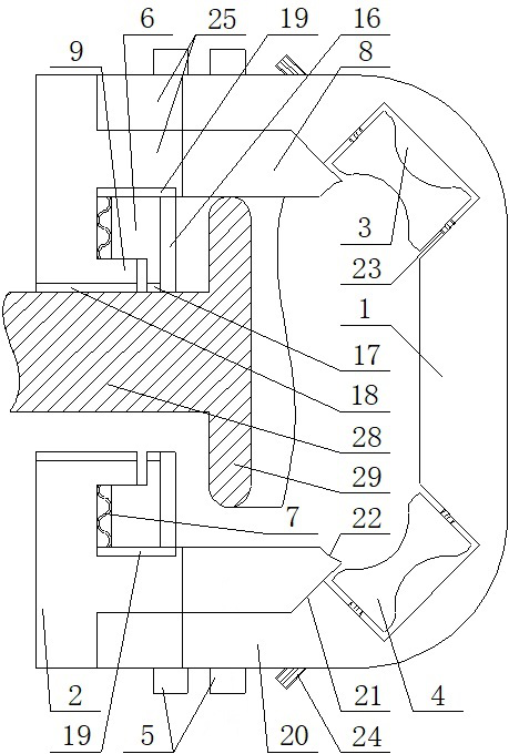
[0033] combine Figure 1~Figure 7 It can be seen that the twisting machine receiving wire device of the present invention includes a "匚" type frame rod 1, and the "匚" type frame rod 1 is located inside the annular retaining ring 29, and the annular retaining ring 29 is connected with the receiving wire of the twisting machine. The material rotating rod moves relative to the axial direction. The end rods 20 on both sides of the "匚" type frame rod 1 are parallel to each other and are respectively located at the two ends of the annular retaining ring 29. The middle part of the outer wall of the annular retaining ring 29 is connected by The plate 28 is connected with the twisting machine, the connecting plate 28 is perpendicular to the axial center of the annular retaining ring 29, and the end rods 20 are respectively detachably and symmetrically fixed with clamping rods 2, and the clamping rods 2 are positioned at the center of the annular retaining ring 29. Outside, and perpendi...


PUM


Abstract

The invention discloses a material collecting yarn guiding device of a twisting machine. [-shaped frame rods are located at the inner side of an annular check ring, clamping rods are detachably and symmetrically fixed to end rods respectively, the clamping rods are located at the outer side of the annular check ring and are perpendicular to the end rods, and the distance A between the clamping rods is larger than the thickness of a connecting plate and smaller than the height of the annular check ring; anti-skid layers A are arranged at the end faces, located in the [-shaped frame rods and facing the outer side wall of the annular check ring, of the clamping rods, and anti-skid layers B are fixed to the opposite end faces of the clamping rods; and column rods are fixed to the bent positions of the inner sides of the [-shaped frame rods respectively, and concave parts are inwards formed in the middles of the surfaces of the side walls of the column rods. According to the structure, thematerial collecting yarn guiding device of the twisting machine can be suitable for different tensions, different yarn diameters and different yarn collecting positions during twisting and yarn collecting of different yarn, and the applicability of the material collecting yarn guiding device of the twisting machine is improved.

Description

technical field [0001] The invention relates to the technical field of a wire receiving device for a twisting machine, in particular to a wire receiving device for a twisting machine. Background technique [0002] Twisting mainly uses a twisting machine for twisting work. In the prior art, when the yarn is taken up, generally the yarn needs to be taken up after being guided by a wire mechanism, but the current wire mechanism is generally similar to the structure disclosed in the patent with the publication number CN208362556U , where the passing coils used for threading are fixed in size. Different yarns and different take-up tensions will produce different forces on the passing coils. Since the passing coils cannot adjust the different tension effects of the yarns, it will cause Different tensions act directly on the take-up reel, and then have different effects on the take-up, and the tension during take-up is directly related to the quality and effect of the take-up of t...

Claims


Application Information

Patent Timeline
IPC IPC(8): D01H13/04
CPCD01H13/04
Inventor 宋杰
Owner 盐城神威制绳有限公司
Features
  • R&D
  • Intellectual Property
  • Life Sciences
  • Materials
  • Tech Scout
  • Unparalleled Data Quality
  • Higher Quality Content
  • 60% Fewer Hallucinations
Learn More