
Scroll compressor

A scroll compressor and moving scroll technology, applied in the field of compressors, can solve problems such as difficulty in starting the scroll compressor, large starting torque, and affecting the normal operation of the compressor, so as to improve the start-up performance, improve the compression effect, Increased sealing effect

Pending Publication Date: 2020-11-03
GUANGDONG MIDEA ENVIRONMENTAL TECH CO LTD
View PDF0 Cites 3 Cited by
  • Summary
  • Abstract
  • Description
  • Claims
  • Application Information

AI Technical Summary

Problems solved by technology

[0003] However, when the compressor stops, the check valve completely isolates the intermediate pressure chamber and the discharge space of the scroll compressor, which leads to the need for a large starting torque when restarting, which leads to difficulty in starting the scroll compressor and affects the compressor. normal operation

Method used


Image

  • Scroll compressor
  • Scroll compressor
  • Scroll compressor

Examples


Embodiment 1

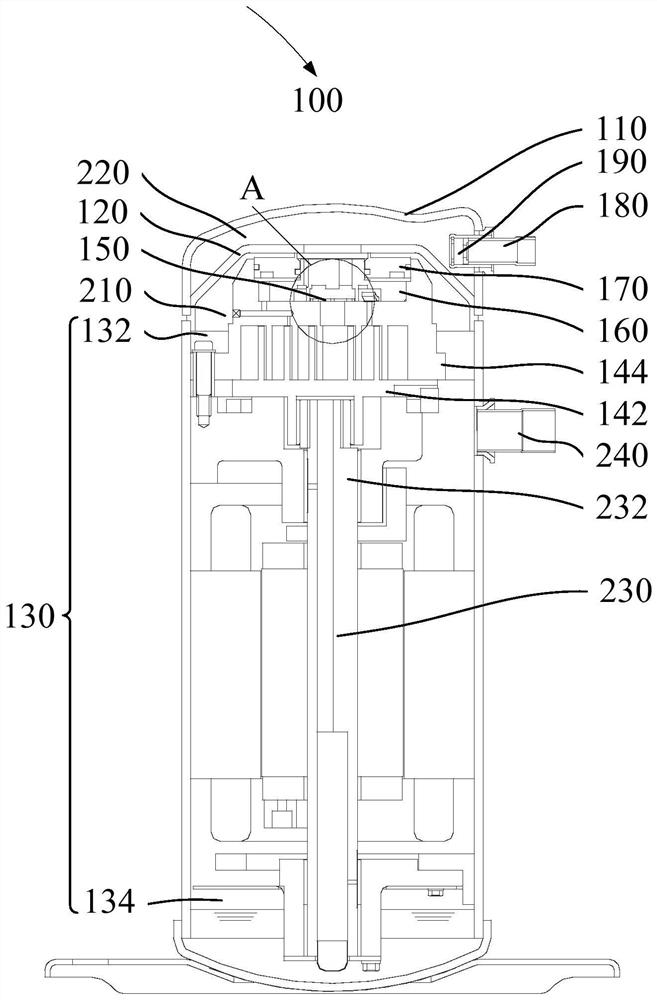
[0049] like figure 1 As shown, according to some embodiments of the present invention, one embodiment of the present invention provides a scroll compressor 100, the scroll compressor 100 includes: casing 110, isolation plate 120, frame 130, movable scroll Disk 142 and fixed scroll 144 .

[0050] Wherein, the casing 110 defines the inner space of the scroll compressor 100 , and an isolation plate 120 is arranged inside the casing 110 , and the inner space of the scroll compressor 100 is divided into a suction space 210 and a discharge space 220 by the isolation plate 120 . The suction space 210 is used to accommodate uncompressed refrigerant, and the discharge space 220 is used to accommodate compressed refrigerant.

[0051] The movable scroll 142 and the fixed scroll 144 are cooperatively arranged in the suction space 210 . The movable scroll 142 and the fixed scroll 144 may cooperate to form: a suction chamber 250 , an intermediate pressure chamber 260 and a discharge chamb...

Embodiment 2

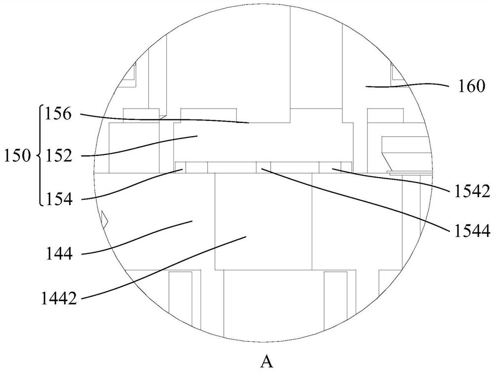
[0056] like Figure 2 to Figure 4 As shown, on the basis of Embodiment 1, further, the pressure relief low return structure 150 includes: a first slideway 152 and a pressure relief low return plate 154 that can slide in the first slideway 152 .

[0057] Specifically, when the movable scroll 142 and the fixed scroll 144 discharge the refrigerant, the pressure relief low return plate 154 is pushed by the refrigerant and moves away from the fixed scroll 144 . At this time, a larger passing area is maintained between the second through hole 1442 and the third through hole 1542 , so that a large amount of refrigerant can quickly enter the discharge space 220 from the second through hole 1442 through the third through hole 1542 .

[0058] And when the movable scroll 142 and the fixed scroll 144 discharge the refrigerant, since the pressure in the discharge space 220 is greater than the pressure between the movable scroll 142 and the fixed scroll 144, specifically, the pressure in th...

Embodiment 3

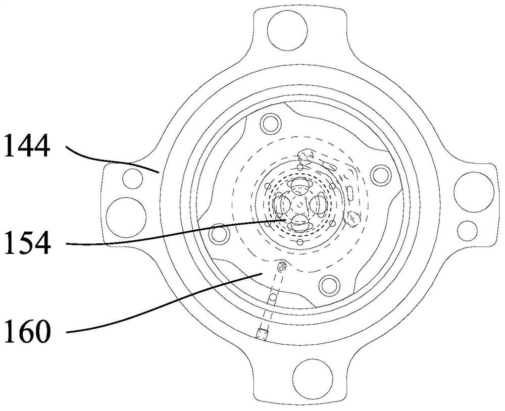
[0063] like Figure 5 As shown, on the basis of Embodiment 1 or Embodiment 2, further, there are multiple passages on the pressure relief low return plate 154 . When the pressure relief low return plate 154 is against the fixed scroll 144, part of the passage can be blocked.

[0064] Specifically, a hole is opened on the pressure relief low return plate 154, and the hole includes a third through hole 1542 and a fourth through hole 1544. When the pressure relief low return plate 154 and the fixed scroll 144 are in contact, the fixed scroll 144 can be blocked. In the third through hole 1542 , only the fourth through hole communicates with the second through hole 1442 and the third through hole 1542 .

[0065] Further, the cross-sectional area of ​​the pressure relief low back plate 154 is greater than the cross-sectional area of ​​the second through hole 1442 . That is, the pressure relief low return plate 154 can be set on the edge of the second through hole 1442 , and the th...


PUM


Abstract

The invention provides a scroll compressor. The scroll compressor comprises a machine shell, an isolation plate, a rack, a movable scroll plate, a static scroll plate and a pressure relief low-speed revolution structure. The isolation plate is arranged in the machine shell and divides the interior of the machine shell into a suction space and a discharge space, and a first through hole is formed in the isolation plate so as to communicate the suction space with the discharge space; the rack is arranged in the machine shell and located in the suction space, and the rack and the isolation plateare arranged at intervals; the movable scroll plate is movably arranged on the rack; the static scroll plate is arranged on the rack and matched with the movable scroll plate, a second through hole isformed in the static scroll plate, and the second through hole is communicated with the discharge space; and the pressure relief low-speed revolution structure is arranged on the static scroll plate,and the pressure relief low-speed revolution structure is configured to be capable of communicating the second through hole with the discharge space. According to the scroll compressor, the movable scroll plate rotates at a low speed when the scroll compressor is stopped, the pressure difference between a middle pressure chamber and the discharge space is balanced, abrasion and abnormal noise caused by high-speed rotation of the movable scroll plate are avoided, a refrigerant can be smoothly discharged into the discharge space when the scroll compressor is restarted, and the starting performance of the scroll compressor is improved.

Description

technical field [0001] The invention relates to the field of compressors, in particular to a scroll compressor. Background technique [0002] In the related art, the static scroll of the scroll compressor is provided with a check valve to avoid the backflow of the discharged refrigerant and the high-speed rotation of the scroll to avoid wear and abnormal noise. [0003] However, when the compressor stops, the check valve completely isolates the intermediate pressure chamber and the discharge space of the scroll compressor, which leads to the need for a large starting torque when restarting, which leads to difficulty in starting the scroll compressor and affects the compressor. normal operation. Contents of the invention [0004] The present invention aims to solve at least one of the technical problems existing in the prior art. [0005] To this end, some embodiments of the present invention provide a scroll compressor. [0006] In view of this, according to some embodi...

Claims


Application Information

Patent Timeline
Patent Type & Authority Applications(China)
IPC IPC(8): F04C18/02F04C23/02F04C29/00
CPCF04C18/0215F04C23/02F04C29/00F04C29/0021
Inventor 黄柏英饗场靖新宅秀信
Owner GUANGDONG MIDEA ENVIRONMENTAL TECH CO LTD
Learn More