System and method for improving terahertz wave nondestructive testing resolution

A non-destructive testing and terahertz wave technology, applied in the detection field, can solve the problems of small dynamic range, difficult Gaussian beam, low signal-to-noise ratio, etc., and achieve the effect of large dynamic range, improved detection resolution and high signal-to-noise ratio

Active Publication Date: 2020-11-03
CHINA ELECTRONIS TECH INSTR CO LTD
View PDF10 Cites 0 Cited by
  • Summary
  • Abstract
  • Description
  • Claims
  • Application Information

AI Technical Summary

Problems solved by technology

[0004] The inventors found that most of the traditional terahertz wave imaging detection technologies are based on Gaussian beams, and it is difficult to have a long depth of field and high resolution. Even if the terahertz wave structured beams appear, they all use a single channel. There are problems such as small dynamic range and low signal-to-noise ratio

Method used


Image

  • System and method for improving terahertz wave nondestructive testing resolution

Examples


Embodiment 1

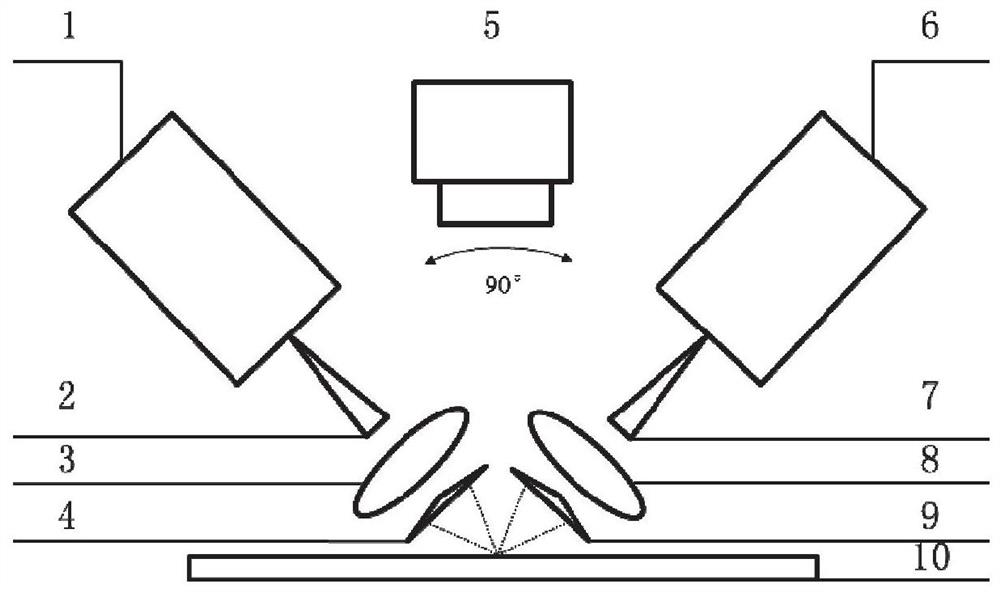
[0024] In a typical embodiment of the present invention, such as figure 1 As shown, this embodiment discloses a system for improving the resolution of terahertz wave non-destructive detection, including: a terahertz wave transmitting module 1 for transmitting terahertz waves, a terahertz wave transmitting module 1 capable of transmitting terahertz waves into free space The transmitting antenna 2, the first terahertz wave focusing element 3 and the second terahertz wave focusing element 8 for converging the terahertz waves emitted from the terahertz wave antenna, and the collimated Gaussian beams for forming a quasi-zero order The first optical element 4 and the second optical element 9 of the Bessel beam, and a laser displacement sensor used to realize the closed-loop control of the distance between the transceiver module and the DUT 10 and ensure that the DUT 10 is at the best focus position 5. The terahertz wave receiving module 6 used to receive the terahertz wave reflected...

Embodiment 2

[0036] In a typical implementation of the present invention, Example 2 provides a method for improving the resolution of terahertz wave nondestructive testing, using the system for improving the resolution of terahertz wave nondestructive testing as described in Example 1, using a terahertz wave The hertz wave transmitting end transmits terahertz waves to the detection area of ​​the measured object for measurement, and the terahertz wave receiving end performs terahertz wave reception on the detection area of ​​the measured object.

[0037] In order to ensure the maximum detection of the signal, the laser displacement sensor 5 is used to ensure that the terahertz wave transceiver module and the measured object are always at the optimal distance, that is, the terahertz wave focusing position, and at the same time, the terahertz wave signal transmitting end and the terahertz wave signal receiving end The placement angle of the terminal can be 90 degrees, and can also be adjusted ...


PUM


Abstract

The invention discloses a system and a method for improving terahertz wave nondestructive detection resolution, and belongs to the technical field of detection. An optical element is added behind a terahertz wave focusing element to generate a quasi-zero-order Bessel wave beam from a collimated Gaussian wave beam so as to achieve relatively long depth of field and relatively high resolution in terahertz wave imaging. A confocal technology is adopted to meet a large dynamic range and a high signal-to-noise ratio, and the system comprises a terahertz wave transmitting end, a terahertz wave receiving end and a laser displacement sensor used for measuring the distance between the terahertz wave transmitting end and a detection area and the distance between the terahertz wave receiving end andthe detection area. The directions of terahertz waves in the terahertz wave transmitting end and the terahertz wave receiving end are different from each other; the terahertz wave transmitting end projects terahertz waves to the detection area, and the terahertz wave receiving end receives the terahertz waves from the detection area; the terahertz wave transmitting end and the terahertz wave receiving end each comprise a focusing element used for terahertz wave focusing and an optical element used for generating a quasi-zero-order Bessel beam.

Description

technical field [0001] The invention belongs to the technical field of detection, and in particular relates to a system and method for improving the resolution of terahertz wave non-destructive detection. Background technique [0002] The statements herein merely provide background information related to the present invention and do not necessarily constitute prior art. [0003] Terahertz waves refer to electromagnetic waves with frequencies in the range of 0.1THz to 10THz and corresponding wavelengths between 3mm and 0.03mm. Like visible light, X-rays, infrared and ultrasound waves, terahertz waves can also be used to image objects. Since terahertz waves can penetrate non-metallic and non-polar materials such as ceramics, graphite, polymer composites, plastics, and foams, it is possible to detect defects, holes, inclusions, debonding, and faults in samples made of these materials. Clear imaging of dislocations and cracks, etc., to achieve non-destructive testing. Compare...

Claims


Application Information

Patent Timeline
Patent Type & Authority Applications(China)
IPC IPC(8): G01N21/3581
CPCG01N21/3581
Inventor 王金榜年夫顺王亚海赵锐常庆功
Owner CHINA ELECTRONIS TECH INSTR CO LTD
Why Eureka
Try Eureka