Pixel driving circuit of Micro LED display device and driving method thereof

A pixel driving circuit and display device technology, applied in static indicators, instruments, etc., can solve problems such as signal coupling, display problems, and inability to achieve continuous adjustment of gray scales, and achieve the effect of avoiding spectrum shift

Inactive Publication Date: 2020-11-03
NANJING CEC PANDA LCD TECH
View PDF11 Cites 2 Cited by
  • Summary
  • Abstract
  • Description
  • Claims
  • Application Information

AI Technical Summary

Problems solved by technology

The existing PWM (Pulse Width Modulation, Pulse Width Modulation) circuit is mainly carried out by adjusting the EM signal, which can only control the light-emitting time of the light-emitting element by inserting pulses within the display time, and the overall brightness of the display can only be in several levels. The continuous adjustment of the gray scale cannot be achieved, and the frequent switching of the EM signal causes the coupling of the signal, which further causes display problems

Method used


Image

  • Pixel driving circuit of Micro LED display device and driving method thereof
  • Pixel driving circuit of Micro LED display device and driving method thereof

Examples


Embodiment Construction

[0032] Below in conjunction with the accompanying drawings and specific embodiments, the present invention will be further clarified. It should be understood that these embodiments are only used to illustrate the present invention and not to limit the scope of the present invention. Modifications of equivalent forms all fall within the scope defined by the appended claims of this application.

[0033] In order to keep the drawings concise, the drawings only schematically show the parts related to the present invention, and they do not represent its actual structure as a product. In addition, in order to make the drawings concise and easy to understand, in some drawings, only one of the components having the same structure or function is schematically shown, or only one of them is marked. As used herein, "one" not only means "only one", but also "more than one".

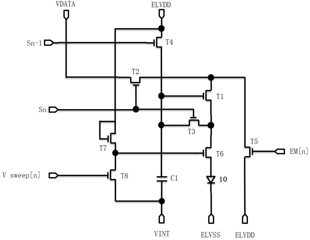
[0034] The Micro LED display device of the present invention includes criss-cross scan lines and data lines, pixel...


PUM


Abstract

The invention provides a pixel driving circuit of a Micro LED display device and a driving method thereof, the pixel driving circuit comprises a first TFT switch, a second TFT switch, a fifth TFT switch, a sixth TFT switch, an eighth TFT switch and a capacitor which are used as driving transistors, and a current row time control signal outputs a triangular wave signal when a current row light emitting unit emits light. According to the pixel driving circuit, Vth compensation can be carried out on the first TFT switch serving as a driving transistor, the light emitting time of a MicroLED can becontinuously adjusted, and the brightness of a panel is adjusted through amplitude modulation and pulse modulation; according to the circuit, the brightness of the panel can be controlled under the condition that a data voltage signal is not adjusted, and MicroLED frequency spectrum offset caused by current density reduction under a low gray scale is avoided.

Description

technical field [0001] The present invention relates to the technical field of Micro LEDs, and in particular, to a pixel driving circuit of a Micro LED display device and a driving method thereof. Background technique [0002] As the next-generation current-mode display light-emitting element, Micro-LED can avoid material degradation and screen burn-in problems of OLED light-emitting devices, and at the same time has ultra-high luminous efficiency. The brightness of conventional OLED displays does not exceed 2000nits. Up to about 107nits. [0003] In addition to the Vth shift compensation of the active device TFT / MOS, the drive circuit of the Micro-LED also needs to ensure a stable current for the Micro-LED chip. Since the drive current of the Micro-LED chip is smaller, the current The stability requirement is much higher than that of OLED devices. In addition, according to recent research, the wavelength of Micro-LED chips will shift with the change of current density. ...

Claims


Application Information

Patent Timeline
Patent Type & Authority Applications(China)
IPC IPC(8): G09G3/32
CPCG09G3/32G09G2320/0626G09G2310/0259
Inventor 王鸣昕高威黄洪涛徐尚君朱景辉朱充沛
Owner NANJING CEC PANDA LCD TECH
Why Eureka
Try Eureka