Backward wave oscillator (BWO)

An oscillator and return wave technology, applied in the field of microwave vacuum devices, can solve problems such as low output power

Inactive Publication Date: 2020-11-03
HUADONG PHOTOELECTRIC TECHN INST OF ANHUI PROVINCE
View PDF7 Cites 2 Cited by
  • Summary
  • Abstract
  • Description
  • Claims
  • Application Information

AI Technical Summary

Problems solved by technology

The return wave oscillator has the advantages of high operating freque

Method used


Image

  • Backward wave oscillator (BWO)

Examples


Embodiment Construction

[0024] Specific embodiments of the present invention will be described in detail below in conjunction with the accompanying drawings. It should be understood that the specific embodiments described here are only used to illustrate and explain the present invention, and are not intended to limit the present invention.

[0025] In the present invention, in the absence of a contrary description, the orientation words included in the term, such as "left, right, inside, outside, middle", etc., only represent the orientation of the term in the normal use state, or are technically known in the art A common term as understood by persons and should not be construed as a limitation of the term.

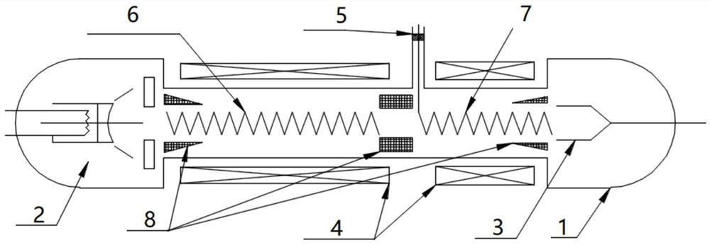
[0026] see figure 1 , the present invention provides a back-wave oscillator, which is a vacuum electronic device, including a shell 1 and an electron gun 2, a high-frequency structure and a collector 3 arranged inside the shell 1 from left to right; A magnetic focusing system 4 is provided ou...


PUM


Abstract

The invention discloses a backward wave oscillator (BWO). Compared with a conventional backward-wave oscillator, the BWO has the advantages that a backward-wave amplification structure is added on thebasis of a backward-wave high-frequency structure, the interaction efficiency of electrons and electromagnetic waves is improved under the condition that voltage and current are not increased, and the final output power of the BWO is improved.

Description

technical field [0001] The invention relates to the field of microwave vacuum devices, in particular to a return wave oscillator. Background technique [0002] In the field of microwaves, microwave oscillators are widely used as microwave signal generators in radar, electronic countermeasures, communications and other fields. Microwave oscillation sources generally include vacuum triodes, reflection klystrons, return wave oscillation tubes, and solid-state devices. [0003] The return wave oscillator is generally composed of an electron gun, a high-frequency structure, a collector pole, a magnetic focusing system, an output window, and a cooling system. The return wave oscillator has the advantages of high operating frequency and wide tuning bandwidth, but the output power is generally small. Contents of the invention [0004] The object of the present invention is to provide a return wave oscillator which can greatly increase the output power. [0005] In order to achi...

Claims


Application Information

Patent Timeline
IPC IPC(8): H01J25/46H01J23/26
CPCH01J25/46H01J23/26H01J2225/46H01J2223/27
Inventor 沈旭东赵艳珩王鹏康
Owner HUADONG PHOTOELECTRIC TECHN INST OF ANHUI PROVINCE
Why Eureka
Try Eureka