Cable anti-damage wall-penetrating bushing protector

An anti-damage and protector technology, applied in the direction of electrical components, etc., can solve the problems of high friction, limited anti-wear effect, and wear of the clamping position of the cable, so as to ensure shock absorption and anti-wear performance, and use The effect of simple and convenient operation and streamlined structure

Inactive Publication Date: 2020-11-03
徐州华显凯星信息科技有限公司
View PDF2 Cites 0 Cited by
  • Summary
  • Abstract
  • Description
  • Claims
  • Application Information

AI Technical Summary

Problems solved by technology

[0002] The cable wall sleeve is a power construction auxiliary accessory used to separate the cables that need to pass through the wall from the wall, so as to avoid direct friction between the cable and the wall when passing through the wall. The cables are worn and damaged, but the traditionally used wall-through sleeves are in the form of straight tubes that are simply placed in the wall holes. For cables with large amplitudes, the sleeves and cables are prone to friction and wear , and the vibration generated by the cable cannot be damped and buffered, resulting in serious wear between the cable and the wall sleeve. The structure is separated from each other, resulting in the clamping position of the shock-absorbing structure to the cable is still prone to wear and tear
[0003] Notification No. CN109103824A discloses a wear-resistant wall-penetrating connection device for power cables. The connection device is a hollow cylinder inside, and the connection device is sequentially provided with elastic first parts coaxial with the connection device from the inside to the outside. A rubber layer and a second rubber layer; four telescopic rods are arranged between the two ends of the first rubber layer and the second rubber layer, and the telescopic rods adjust the first rubber layer, the second rubber layer and the second rubber layer through stretching. The distance between the rubber layer and the connecting device; the cable passes through the first rubber layer, and the diameter of the first rubber layer is adjusted by adjusting the length of the telescopic rod, so that the cable is fixed in the first rubber layer; the first rubber layer and the second rubber layer The distance between the two rubber layers is not less than one-half of the diameter of the cable; there are several first spring rods connected between the second rubber layer and the connecting device, and the device is protected against wear through the rubber layer, but the cable The friction between the rubber layer and the rubber layer is still sliding friction, and the friction force that causes wear is relatively large, resulting in limited anti-wear effect

Method used


Image

  • Cable anti-damage wall-penetrating bushing protector
  • Cable anti-damage wall-penetrating bushing protector
  • Cable anti-damage wall-penetrating bushing protector

Examples


Embodiment 1

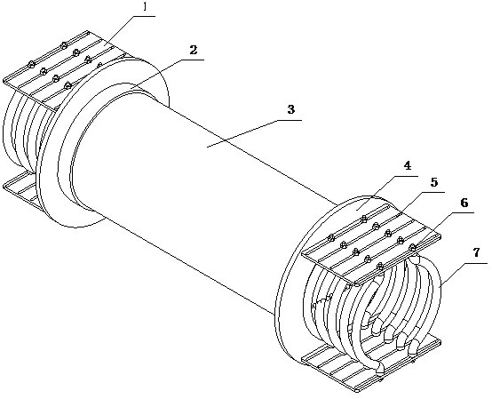
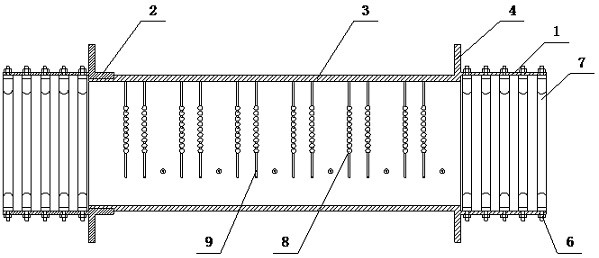
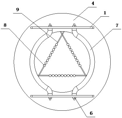
[0020] An anti-damage wall-piercing sleeve protector for cables of the present invention is realized in the following way: a cable-damage-proof wall-penetrating sleeve protector of the present invention consists of a fixing plate (1), a connecting sleeve (2), and a main sleeve ( 3), the limit plate (4), the chute (5), the locking screw (6), the guide hoop (7), the ball (8) and the support rib (9), and the connecting sleeve (2) is screwed respectively On one end of the main casing (3), a limiting plate (4) is fixed on the other end of the main casing (3), between the limiting plate (4) and the wall of the main casing (3) The included angle is an acute angle, and the limiting plate (4) is fixed on the connecting sleeve (2). The included angle between the limiting plate (4) and the wall of the connecting sleeve (2) is an acute angle, and the two fixing plates (1) Symmetrically placed on the limit plate (4), the fixed plate (1) is provided with a plurality of equidistantly distrib...

Embodiment 2

[0023] The difference between this embodiment and Embodiment 1 is that one pair of guide hoops (7) is increased into two pairs, and the two ends of the guide hoops (7) are provided with connecting shafts (10), and the two pairs of guide hoops (7) ) on the connecting shaft (10) is connected through the fixed piece (11), and the fixed piece (11) is connected with the locking screw (6); when in use, the two pairs of guide hoops (7) can be rotated and adjusted according to the bending requirements ) to improve the arc fineness of its guide bending;

[0024] The angle between the limiting plate (4) and the wall of the main casing (3) is an acute angle, and the angle between the limiting plate (4) and the wall of the connecting sleeve (2) is an acute angle design. During installation, it can elastically push the wall and enhance the connection strength of the protective structure;

[0025] The chute (5) is designed as a long trough, so that the guide hoop (7) can slide in the chute...


PUM


Abstract

The invention discloses a cable anti-damage wall-penetrating bushing protector, and discloses a protection structure which combines a damping structure and an anti-abrasion structure into a whole, simplifies the structure and ensures the damping and anti-abrasion performance at the same time. Connecting sleeves are respectively screwed at one end of a main bushing, and a limiting plate is fixedlyarranged at the other end of the main bushing; the included angle between the limiting plate and the wall of the main sleeve is an acute angle, the limiting plate is fixedly arranged on the connectingsleeve, the included angle between the limiting plate and the wall of the connecting sleeve is an acute angle, the two fixing plates are symmetrically arranged on the limiting plate, a plurality of long-bar-shaped sliding grooves distributed at equal intervals are formed in the fixing plates; a plurality of pairs of guide hoops are arranged between the two fixing plates and correspond to the sliding grooves in a one-to-one mode, wherein each guide hoop is of an arc-shaped rod-shaped structure; an elastic pad is arranged on the arc-shaped concave face of each guide hoop, the two ends of each guide hoop are bent back to back in the vertical direction, and the two ends of each guide hoop are arranged in the corresponding sliding grooves through locking screws respectively.

Description

technical field [0001] The invention relates to an anti-damage wall-penetrating sleeve protector for cables, which relates to a sleeve protection structure for preventing cable damage when cables pass through walls in a shop, and belongs to the field of electric equipment. In particular, it relates to a protection structure which combines a shock absorbing structure and an anti-wear structure into one, and simplifies the structure while ensuring shock absorbing and anti-wear performances. Background technique [0002] The cable wall sleeve is a power construction auxiliary accessory used to separate the cables that need to pass through the wall from the wall, so as to avoid direct friction between the cable and the wall when passing through the wall. The cables are worn and damaged, but the traditionally used wall-through sleeves are in the form of straight tubes that are simply placed in the wall holes. For cables with large amplitudes, the sleeves and cables are prone to f...

Claims


Application Information

Patent Timeline
Patent Type & Authority Applications(China)
IPC IPC(8): H02G3/22
CPCH02G3/22
Inventor 不公告发明人
Owner 徐州华显凯星信息科技有限公司
Why Eureka
Try Eureka