Cavity guide wire

A guide wire and cavity technology, applied in the field of medical devices, can solve the problems of increasing the surface friction coefficient of the distal end of the guide wire, unfavorable operator judgment and operation, and reducing the support of the distal end of the guide wire, and achieves good mechanical feedback, Good passability, smooth and uniform outer surface

Active Publication Date: 2020-11-06
SHANGHAI HEARTCARE MEDICAL TECH CORP LTD
View PDF5 Cites 0 Cited by
  • Summary
  • Abstract
  • Description
  • Claims
  • Application Information

AI Technical Summary

Problems solved by technology

The existing conventional guide wire has the following disadvantages: 1. The guide wire is composed of a rod body and a distal spring, and the strength of the physical connection between the two is limited. , glue bonding and other connection methods introduce materials such as solder and glue, which may cause allergic reactions in patients with specific constitutions; Indirect, and because the spring itself has a certain degree of elasticity, when the distal end of the guide wire touches the blood vessel wall or hardened plaque or thrombus in the blood vessel, the contact force will not be accurately and timely fed back to the proximal end of the guide wire, which is not conducive to the operator's judgment and operation; 3. In order to make the distal end of the guide wire have a certain degree of flexibility, the distal end of the guide wire is usually ground to obtain a smaller diameter than the proximal end, but this will lead to a decrease in the support of the distal end of the guide wire; 4 .The diameter of the distal end of the guide wire after grinding is smaller than that of the proximal end. When the proximal end is rotated during use, the torque cannot be effectively transmitted to the distal end. The rotation of the distal end has a larger lag angle than that of the proximal end. 5. The outer winding spring will make the surface of the distal end of the guide wire uneven, thereby increasing the friction coefficient of the distal end of the guide wire, which may cause damage to the vessel wall during use, and bring unpredictable risks to the patient

Method used


Image

  • Cavity guide wire
  • Cavity guide wire
  • Cavity guide wire

Examples


Embodiment 1

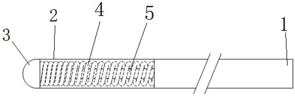
[0031] Such as figure 1, as shown in 2, is a structural schematic diagram of a guide wire of the present invention, the guide wire has an integral structure from the guide wire proximal end 1 to the guide wire distal end 2 and the head end 3, and the head end 3 is designed in a dome shape. The proximal end 1 of the guide wire is equal to the diameter of the distal end 2 of the guide wire. When the proximal end 1 of the guide wire is rotated, the torque can be transmitted to the distal end 2 of the guide wire and the tip 3 of the guide wire in a timely manner, thus having good torque control; And because the guide wire is an integral structure, the guide wire tip 3 and the guide wire distal end 2 can directly and effectively transmit the received force to the guide wire proximal end 1 during use; the diameter of the guide wire distal end 2 is compared with that of the guide wire near End 1 is not reduced, so it has better support and is more suitable for cooperation with other ...

Embodiment 2

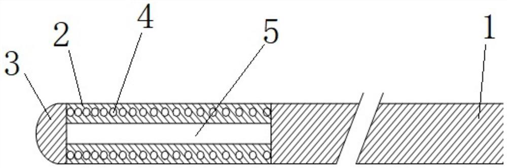
[0035] Such as image 3 shown, is figure 1 and figure 2 A cross-sectional view of an improved form of the guide wire shown in , the guide wire is an integral structure from the guide wire proximal end 1 to the guide wire distal end 2 and the head end 3, the head end 3 is designed in a dome shape, and the guide wire near End 1 and distal end 2 are equal in diameter.

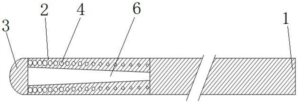
[0036] The shaded part in the figure is the entity, and the rest are the helical cavity 4 and the conical cavity 6. The diameter of the helical cavity 4 and the cross-sectional diameter of the cavity are from the part close to the proximal end 1 of the guide wire to the part close to the guide wire. The portion of the distal end 2 increases gradually, while the pitch of the helix gradually decreases; meanwhile, the diameter of the conical cavity 6 gradually increases from the portion close to the proximal end 1 of the guide wire to the portion close to the distal end 2 of the guide wire.

[0037] This improved...

Embodiment 3

[0039] Such as Figure 4 As shown, it is a schematic cross-sectional view of a guide wire with a cavity structure inside the distal end. The guide wire has an integral structure from the proximal end 1 of the guide wire to the distal end 2 of the guide wire and the head end 3 of the guide wire. The head end 3 is Dome-shaped design, the diameter of the proximal end 1 of the guide wire is equal to that of the distal end 2 of the guide wire.

[0040] The shaded part in the figure is a solid, and the rest is a cavity. The cavity is a combined cavity of a conical cavity 6 and an annular cavity 7, from 1 near the proximal end of the guide wire to 2 near the distal end of the guide wire. , due to the increase in the volume of the cavity, the degree of reduction in the structural stress of the guidewire entity along the guidewire axis is further expanded, so that the distal end 2 of the guidewire is compared to figure 1 / figure 2 and image 3 The guidewire shown in has more excel...


PUM


Abstract

The invention relates to a cavity guide wire, and belongs to the technical field of medical instruments. The cavity guide wire comprises a guide wire far-end and a guide wire near-end; the whole guidewire from the guide wire far-end away from an operator and the guide wire near-end close to the operator is designed into an integral cylindrical structure; a dome-shaped head end is arranged at theend head of the guide wire far-end; and a cavity for enabling the guide wire far-end to have flexibility is arranged in the guide wire far-end, the head end of which is close to one side of the operator. According to the cavity guide wire in the invention, the guide wire far-end and near-end are of an integral structure; the design that a spring is arranged at the conventional guide wire far-end is abandoned; the separation risk of the two due to the fact that the connection strength between the spring of the conventional guide wire far-end and the rod body is insufficient is avoided; simultaneously, the mechanical feedback is good; compared with the near-end, the guide wire far-end is relatively flexible due to the interval cavity structure of the guide wire far-end; the guide wire is uniform in diameter; compared with the conventional guide wire, the torsion control and the supportability are greatly improved; the outer surface of the guide wire is a regular cylinder; and, compared with the conventional guide wire, the friction coefficient is relatively small.

Description

technical field [0001] The invention relates to a cavity guide wire and belongs to the technical field of medical instruments. Background technique [0002] With the continuous progress and development of modern medical technology, various interventional operations including thrombectomy, balloon dilation, thrombus filter, occluder stent implantation, etc. are widely used in the diagnosis and treatment of human diseases. Surgery has the advantages of less trauma and low risk. The guide wire is one of the most commonly used medical devices in interventional surgery. It usually enters the blood vessels of the human body first, and with the assistance of ultrasound, X-ray and other medical imaging technologies, it reaches the target site and establishes an interventional surgical pathway to guide other interventional devices or implants. The implanted device reaches the target site for diagnosis or treatment. The existing conventional guide wire structure generally consists o...

Claims


Application Information

Patent Timeline
IPC IPC(8): A61M25/09
CPCA61M25/09A61M2025/09058A61M2025/09175
Inventor 曹维拯周而辰宗耀辉李志刚王国辉
Owner SHANGHAI HEARTCARE MEDICAL TECH CORP LTD
Why Eureka
Try Eureka