Compound mold for forging automobile crankshaft

A compound mold and crankshaft technology, which is applied in the manufacture of tools, casting molding equipment, casting molds, etc., can solve the problems of mold eccentric scrapping, mold folding, uneven distribution of forging liquid, etc., and achieve the effect of improving the quality of workpieces and filling them full

Inactive Publication Date: 2020-11-06
艾凤英
View PDF7 Cites 1 Cited by
  • Summary
  • Abstract
  • Description
  • Claims
  • Application Information

AI Technical Summary

Problems solved by technology

[0004] Aiming at the deficiencies in the prior art, the object of the present invention is to provide a composite mold for forging automobile crankshafts, so as to solve the problem that when the automobile crankshafts are subjected to injection molding, the upper mold and the lower mold are used to extrude the mould, and the forging liquid is When injection molding into the mold groove, most of the forging liquid will accumulate in the middle position, resulting in uneven distribution of the forging liquid inside the mold groove, resulting in deviation of the wall thickness of the mold after injection molding, making the outer chamfer of the product not full , thus affecting the quality of the workpiece produced by forging, and when the upper mold and the lower mold are injecting the crankshaft, they will slip due to the transportation of the forging liquid, and the upper mold and the lower mold will segregate during the processing process, resulting in Defects such as folds and cracks will occur in the mold, which will make the mold eccentric and scrapped, increase the processing cost of the crankshaft, and reduce the processing efficiency of the crankshaft

Method used


Image

  • Compound mold for forging automobile crankshaft
  • Compound mold for forging automobile crankshaft
  • Compound mold for forging automobile crankshaft

Examples


Embodiment 1

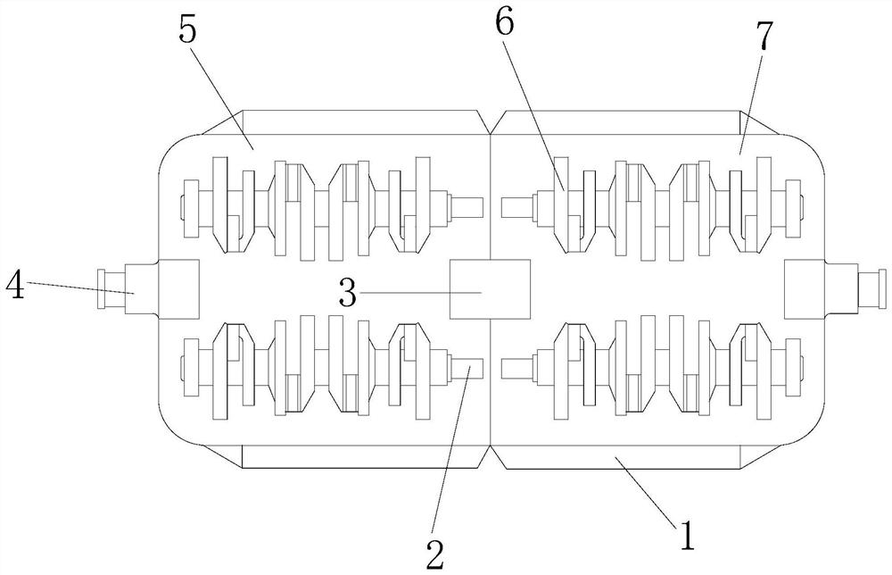
[0035] see figure 1 , the present invention provides a technical solution: an automobile crankshaft forging composite mold, the structure of which includes an adjusting device 1, a fixed shaft 2, a connecting fastener 3, a clamping rod 4, an upper mold 5, an injection cavity 6, and a lower mold 7. The adjusting device 1 is arranged at the bottom of the injection cavity 6, and the upper mold 5 and the lower mold 7 are all provided with an injection cavity 6, and the injection cavity 6 is fitted on the upper mold 5 and the lower mold 7, and the injection cavity 6 One end is provided with a fixed shaft 2, and the fixed shaft 2 is nested inside the injection molding cavity 6, and the upper mold 5 and the lower mold 7 are closely fitted by connecting fasteners 3, and the upper mold 5 and the lower mold 7 form an axis of symmetry structure, the upper mold 5 and the lower mold 7 are fastened through the clamping rod 4, and the clamping rod 4 is inserted and embedded in the side of t...

Embodiment 2

[0051] see figure 1 , the present invention provides a technical solution: an automobile crankshaft forging composite mold, the structure of which includes an adjusting device 1, a fixed shaft 2, a connecting fastener 3, a clamping rod 4, an upper mold 5, an injection cavity 6, and a lower mold 7. The adjusting device 1 is arranged at the bottom of the injection cavity 6, and the upper mold 5 and the lower mold 7 are all provided with an injection cavity 6, and the injection cavity 6 is fitted on the upper mold 5 and the lower mold 7, and the injection cavity 6 One end is provided with a fixed shaft 2, and the fixed shaft 2 is nested inside the injection molding cavity 6, and the upper mold 5 and the lower mold 7 are closely fitted by connecting fasteners 3, and the upper mold 5 and the lower mold 7 form an axis of symmetry structure, the upper mold 5 and the lower mold 7 are fastened through the clamping rod 4, and the clamping rod 4 is inserted and embedded in the side of t...


PUM


Abstract

The invention discloses a compound mold for forging an automobile crankshaft. The compound mold structurally comprises an adjustment device, a fixing shaft, a connecting buckle, a clamping rod, an upper mold, an injection molding cavity and a lower mold. When the compound mold is improved for use, the upper mold and the lower mold are fixedly clamped through mounting clamping blocks; friction force generated between the upper mold and the lower mold is increased through a blocking friction plate, so that the upper mold and the lower mold cannot move on the injection mold; and a worker adjustsa rolling rotating wheel, two clamping sleeves are pulled inwards, and it is guaranteed that the upper mold and the lower mold can be steadily superposed together. The worker presses the upper mold and the lower mold, bouncing rods can be stressed to bounce back, so that the upper mold and the lower mold can vibrate; the vibration amplitude of a vibrating guide plate is controlled through bracingrods and a cushion plate, and the phenomenon that a forging compound overflows is prevented; a swing wheel drives a vibrating cavity to swing through traction of a pull rope, and the forging compoundcan be uniformly distributed inside the injection molding cavity; and quality of workpieces obtained after forging production is improved.

Description

technical field [0001] The invention relates to the field of molds, in particular to a composite mold for forging an automobile crankshaft. Background technique [0002] The car is driven by the engine, and the crankshaft is the key component that converts the linear motion of the piston in the engine into a circular motion. Therefore, the crankshaft has sufficient strength and rigidity, and the surface of the journal must be wear-resistant, work evenly, and have good balance. The cavity structure of the crankshaft is the crankcase. The crankcase is divided into an upper crankcase and a lower crankcase. The lower crankcase is mainly used for lubrication, while the upper crankcase is integrally cast with the cylinder block and connected with the gearbox so that the crankshaft force is transmitted to the gearbox. When injection molding crankshafts, areas for improvement: [0003] In the injection molding of automobile crankshafts, the upper and lower dies are used to extrude...

Claims


Application Information

Patent Timeline
Patent Type & Authority Applications(China)
IPC IPC(8): B22C9/20B22C9/22B22D27/08
CPCB22C9/20B22C9/22B22D27/08
Inventor 艾凤英
Owner 艾凤英
Why Eureka
Try Eureka