Amphibious vehicle and bottom plate compensation and trim adjustment device thereof

A trim adjustment, amphibious technology, applied to amphibious vehicles, motor vehicles, transportation and packaging, etc., can solve the problems of resistance and sailing stability, insufficient drag reduction effect, high weight density of amphibious vehicles, etc., to increase Sailing stability, drag reduction and energy saving effects are obvious, and the effect of improving vehicle navigation performance

Active Publication Date: 2020-11-06
TIANJIN UNIV
View PDF6 Cites 2 Cited by
  • Summary
  • Abstract
  • Description
  • Claims
  • Application Information

AI Technical Summary

Problems solved by technology

[0002] Amphibious vehicles are becoming more and more high-speed, but compared with ordinary boats, amphibious vehicles have a higher weight density and a deeper draft, and due to the layout requirements of the wheels and other structures, the vehicle body cannot present a complete streamlined shape. However, most amphibious vehicles adopt wheel rotation or vertical lifting structure, and the drag reduction effect is not sufficient for the sailing conditions after the speed is significantly increased; in addition, because the overall length and width ratio of the amphibious vehicle is small, it is prone to excessive pitch angle during high-speed navigation. Large and unstable phenomenon, which has a great influence on resistance and sailing stability

Method used


Image

  • Amphibious vehicle and bottom plate compensation and trim adjustment device thereof
  • Amphibious vehicle and bottom plate compensation and trim adjustment device thereof
  • Amphibious vehicle and bottom plate compensation and trim adjustment device thereof

Examples


Embodiment Construction

[0034] The present invention will be further described below in conjunction with the accompanying drawings.

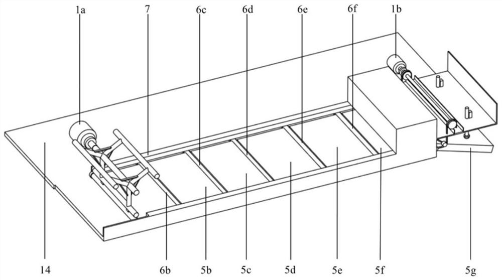
[0035] Such as figure 1 As shown, the floor compensation and pitch adjustment device of the amphibious vehicle of the present invention mainly includes a guide rail 7, a panel unit recovery structure, a panel unit pull-out and reception, a pitch adjustment structure and an integrated controller.

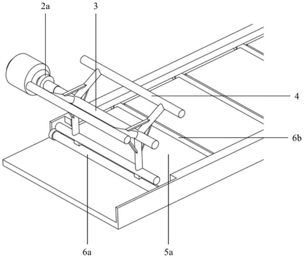
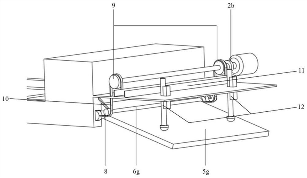
[0036] The guide rails 7 are arranged in two, parallel to each other, respectively located on both sides of the bottom of the rear wheel of the vehicle, arranged close to the bottom surface of the vehicle floor 14, and the front ends of the guide rails 7 extend to the inside of the main vehicle body 17, ensuring that the vehicle floor 14 at this position is compensated. The end of the guide rail 7 is set as a semi-closed structure, allowing the chain 10 to pass through while preventing the No. 7 plate unit connecting shaft 6g from slipping out. Between the two guide rails 7,...


PUM


Abstract

The invention discloses an amphibious vehicle and a bottom plate compensation and trim adjustment device thereof. The bottom plate compensation and trim adjustment device comprises guide rails, a plate unit recovery structure, a plate unit pull-out receiver, a trim adjustment structure and an integrated controller. A first plate unit connecting shaft, a second plate unit connecting shaft, a thirdplate unit connecting shaft, a fourth plate unit connecting shaft, a fifth plate unit connecting shaft, a sixth plate unit connecting shaft and a seventh plate unit connecting shaft are arranged between the guide rails. A first compensation plate unit, a second compensation plate unit, a third compensation plate unit, a fourth compensation plate unit, a fifth compensation plate unit and a sixth compensation plate unit are arranged between the adjacent connecting shafts, and seventh plate unit connecting shafts are connected with a seventh compensation plate unit; the plate unit recovery structure comprises a front-end side-mounted motor, a front-end electric control coupling clutch, a reel and a recovery frame; the plate unit pull-out structure comprises a rear-end side-mounted motor, a rear-end electric control coupling clutch, a driving chain wheel, a transition chain wheel, a chain and a chain box; the trim adjustment structure is composed of an electric hydraulic push rod set.

Description

technical field [0001] The present invention relates to the technical field of design of drag reduction and energy-saving devices for water sports of high-speed amphibious vehicles, in particular to a drag reduction device including integrity compensation of the vehicle floor and an adjustable tail spoiler, and more specifically relates to a An amphibious vehicle and a bottom plate compensation and trim adjustment device thereof. Background technique [0002] Amphibious vehicles are becoming more and more high-speed, but compared with ordinary boats, amphibious vehicles have a higher weight density and a deeper draft, and due to the layout requirements of the wheels and other structures, the vehicle body cannot present a complete streamlined shape. However, most amphibious vehicles adopt wheel rotation or vertical lifting structure, and the drag reduction effect is not sufficient for the sailing conditions after the speed is significantly increased; in addition, because the ...

Claims


Application Information

Patent Timeline
IPC IPC(8): B60F3/00
CPCB60F3/003B60F3/0038Y02T70/10
Inventor 于蕾
Owner TIANJIN UNIV
Why Eureka
Try Eureka