Cloth rolling device for garment production

A technology for fabrics and garments, applied in the field of fabric rolling devices for garment production, can solve problems such as errors, inconvenience in removing fabrics, and consistent lengths of reeled fabrics, so as to achieve good rewinding work, maintain rewinding lengths, and maintain consistency. Effect

Active Publication Date: 2020-11-06
山东靓华制衣有限公司
View PDF8 Cites 18 Cited by
  • Summary
  • Abstract
  • Description
  • Claims
  • Application Information

AI Technical Summary

Problems solved by technology

[0006] In order to overcome the disadvantages that the existing cloth rolling equipment is inconvenient to remove the rolled cloth, the cloth needs to be cut manually, the length of the cloth cannot be kept consistent each time, and there are errors. The technical problem is to provide a fabric rolling device for garment production that can easily remove the rolled fabric, keep the fabric rolling length consistent, and automatically cut the fabric

Method used


Image

  • Cloth rolling device for garment production
  • Cloth rolling device for garment production
  • Cloth rolling device for garment production

Examples


Embodiment 1

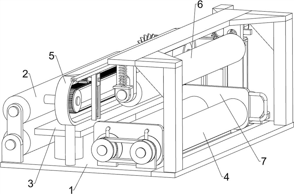
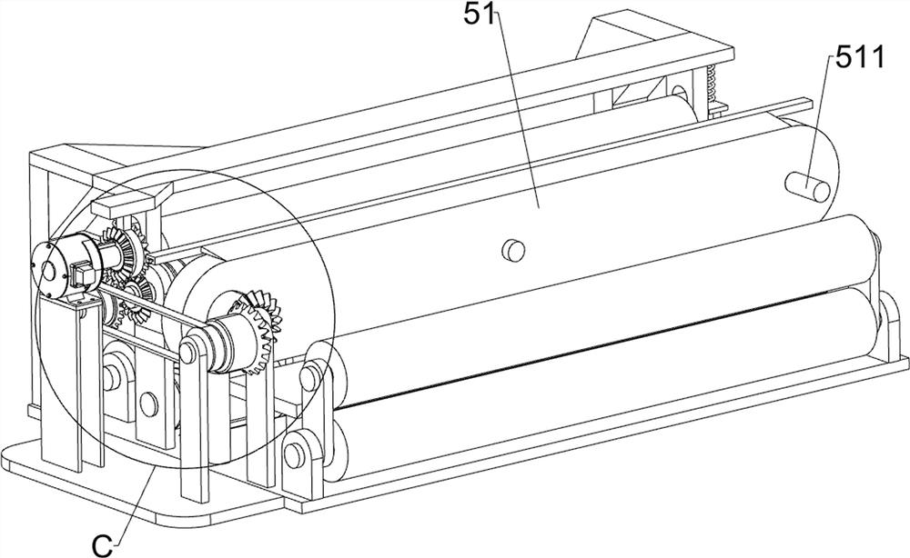
[0026] A cloth rolling device for garment production, such as Figure 1-7 As shown in the figure, it includes a bottom plate 1, a limit roller 2, a spreading platen 3, a rolling mechanism 4 and a cutting mechanism 5. The top left side of the bottom plate 1 is rotatably connected with two limit rollers 2. The two limit The rotating roller 2 is symmetrical up and down, the top of the bottom plate 1 is connected with a cloth spreading platen 3, the cloth spreading platen 3 is located on the right side of the limit rotating roller 2, and the top of the bottom plate 1 is respectively equipped with a rolling mechanism 4 and a cutting mechanism 5.

[0027] The winding mechanism 4 includes a first drum 41 , a second drum 42 , a first transmission belt group 43 , a fixed baffle 44 , a second transmission belt group 45 , a mounting plate 46 , a first bevel gear 47 , and a double-head bevel gear 48 and servo motor 49, a fixed baffle 44 is connected to the top right front side of the bott...

Embodiment 2

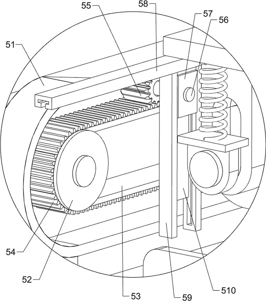
[0031] On the basis of Example 1, as figure 1 , figure 2 , image 3 , Figure 5 and Figure 7As shown, a trigger mechanism 6 is also included. The trigger mechanism 6 includes a mounting frame 61, a sliding roller 62, a guide block 63, a connecting block 64, a support spring 65, a wedge push rod 66, a sliding collar 67, and a second bevel gear. 68. The third drive belt set 69, the third bevel gear 610, the fourth bevel gear 611 and the fixing frame 612, the mounting frame 61 is connected to the right side of the top of the bottom plate 1, and the front and rear sides of the inner top of the mounting frame 61 are connected with guide blocks 63, a connecting block 64 is slidably connected between the two guide blocks 63, a sliding roller 62 is rotatably connected in the middle of the connecting block 64, and two supporting springs 65 are connected between the top of the connecting block 64 and the inner top of the mounting frame 61, The two support springs 65 are symmetrica...

Embodiment 3

[0034] On the basis of Example 2, as figure 1 As shown, it also includes a width adjustment plate 7, the top right side of the bottom plate 1 is slidably connected with the width adjustment plate 7, and the width adjustment plate 7 is slidably and rotatably connected with the first roller 41 and the second roller 42.

[0035] The width adjustment plate 7 can be moved so that the width adjustment plate 7 is in contact with the reel, so that the reel can better perform the cloth winding work.


PUM


Abstract

The invention relates to a rolling device, in particular to a cloth rolling device for garment production. Through the provided cloth rolling device for garment production, rolled cloth can be taken down conveniently, cloth rolling lengths can be kept consistent, and the cloth can be cut off automatically. The cloth rolling device for garment production comprises a bottom plate, a cloth spreadingtable plate, a rolling mechanism and a cut-off mechanism. Two limiting rotary rollers are rotationally connected to one side of the bottom plate. The cloth spreading table plate is connected to the side, close to the limiting rotary rollers, of the bottom plate. The rolling mechanism is installed on the bottom plate. The cut-off mechanism is installed on the bottom plate. According to the cloth rolling device, a reel can rotate to roll the cloth, the cloth can be cut off by the cut-off mechanism, a trigger mechanism can assist the rolling mechanism and the cut-off mechanism in work, and thus rolling work can be conducted better.

Description

technical field [0001] The invention relates to a roll-up device, in particular to a fabric roll-up device for garment production. Background technique [0002] Cloth is a commonly used material in decorative materials, including chemical fiber carpets, non-woven wall coverings, linen cloth, nylon cloth, colored tape, flannel and other fabrics. The main force that cannot be ignored in the sales space, a large number of fabrics are used for wall decoration, partition, and background treatment, which can also form a good commercial space display style. Longer fabrics are rolled up. [0003] After searching, the patent publication number is: CN210504874U, which discloses a glass fiber cloth winding device, including side plates and a bottom plate; the side plates are provided with two and symmetrically installed on the bottom plate, between the two side plates A take-up roller fixedly connected with the motor output shaft is provided, and the upper end of the take-up roller i...

Claims


Application Information

Patent Timeline
Patent Type & Authority Applications(China)
IPC IPC(8): B65H18/16B65H19/30B65H19/26
CPCB65H18/16B65H19/30B65H19/265
Inventor 陈美华
Owner 山东靓华制衣有限公司
Why Eureka
Try Eureka