Filling device for cosmetic production

A filling device and cosmetic technology, applied in the field of filling devices for cosmetic production, can solve the problems of easily overflowing filling bottles, foam accumulation, insufficient filling volume, etc., to ensure reliability, avoid foam accumulation, and improve uniformity Effect

Active Publication Date: 2020-11-06
济宁高新文化创意园服务有限公司
View PDF17 Cites 1 Cited by
  • Summary
  • Abstract
  • Description
  • Claims
  • Application Information

AI Technical Summary

Problems solved by technology

With the development of fully automatic technology, the filling equipment in the packaging equipment has received more and more attention in the market. The safe filling of the entire production line has a great impact on the quality, but the existing liquid cosmetics The filling equipment mainly uses the motor to drive the filling head into the filling bo

Method used


Image

  • Filling device for cosmetic production
  • Filling device for cosmetic production
  • Filling device for cosmetic production

Examples


Embodiment 1

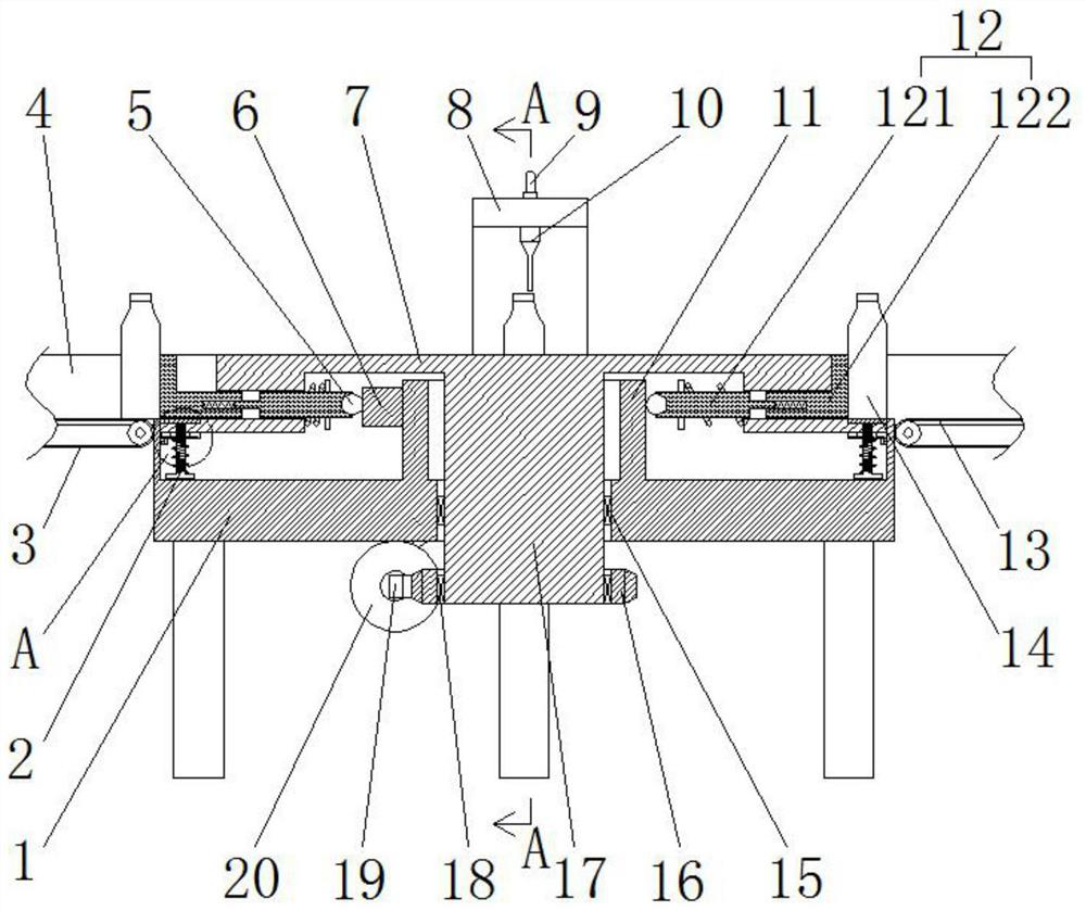
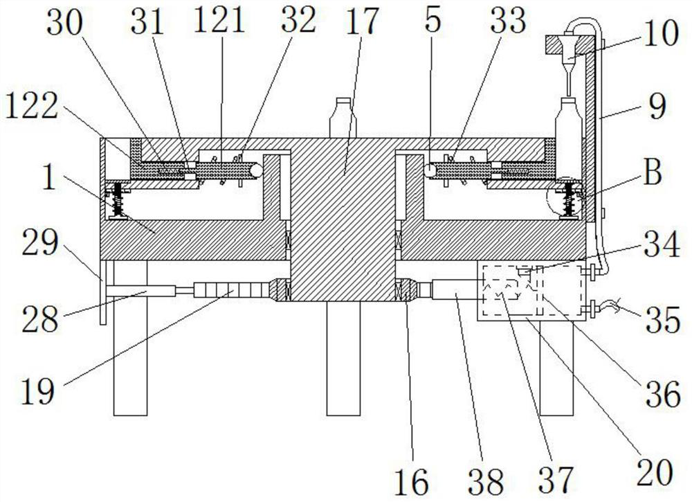
[0029] Such as figure 1 , image 3 and Figure 5 The shown filling device for cosmetics production includes a conveying mechanism for conveying filling bottles 14 and a filling mechanism for filling liquid cosmetics. Filling head 10; the conveying mechanism includes a fixed support platform 1 with supporting legs at the bottom and a rotatable rotary platform 7 located at the upper end of the fixed support platform 1, the fixed support platform 1 is in a circular groove shape, And the center of its inner side is fixed with a support cylinder 11 supported under the turntable 7, and the center of the bottom surface of the turntable 7 is fixed with a central rotating shaft that vertically passes through the inner side of the support cylinder 11 and extends to the bottom of the fixed support platform 1. 17, the lower end of the central rotating shaft 17 is connected to a rotation drive mechanism;

[0030] The two opposite sides of the upper end of the fixed support table 1 are r...

Embodiment 2

[0042] The difference between this embodiment and embodiment 1 is:

[0043] In this example, if image 3 As shown, the energization switch 34 is arranged on one side of the cavity of the storage cylinder 20 corresponding to the side where the telescopic rod 38 is located, and the energization switch 34 is provided with a slope for the telescopic rod 38 to interfere. In the initial state, the energization The switch 34 is located between the telescoping rod 38 and the piston plate 36 . Before the telescopic rod 38 moves to contact the piston plate 36, it will first conflict with the slope of the power switch 34, and then as the telescopic rod 38 continues to move, the power switch 34 can be pressed to energize the static contact 39; When the reset moves to break away from the energization switch 34, the energization switch 34 can reset automatically. Then there is no need to additionally press the energization switch 34 to energize the static contact 39 .

[0044] Others are...


PUM


Abstract

The invention discloses a filling device for cosmetic production, and belongs to the field of cosmetic production equipment. The filling device comprises a conveying mechanism and a filling mechanism,wherein the filling mechanism comprises a storage barrel and a filling head communicated with the storage barrel; the conveying mechanism comprises a fixed supporting table and a rotating table; a feeding notch, a filling station and a discharging notch are sequentially formed in the three sides of the fixed supporting table, carrier plates used for bearing filling bottles are arranged on the rotating table at equal intervals, and lifting rods are fixed to the bottoms of the carrier plates and are connected with a rotating lifting driving mechanism; the outlet end of the filling head is aligned with the eccentric part of a bottle opening of a filling bottle at the filling station; pushing assemblies in one-to-one correspondence with the carrier plates are arranged on the rotating table, and arc-shaped protruding blocks which are gradually widened are fixed to the outer side face of the supporting barrel. A large amount of foam can be prevented from being generated in the filling bottle, so that insufficient filling amount caused by foam accumulation in the filling bottle can be avoided, and the reliability of the filling procedure is guaranteed; and automatic feeding, filling anddischarging can be achieved, and the working efficiency is high.

Description

technical field [0001] The invention relates to the field of cosmetic production equipment, in particular to a filling device for cosmetic production. Background technique [0002] Cosmetics refer to smearing, spraying or other similar methods that are spread on any part of the human body surface, such as skin, hair, nails, lips and teeth, etc., to achieve cleaning, maintenance, beauty, modification and change of appearance, or to correct human body odor, maintain Chemical industrial products or fine chemical products for the purpose of good condition. In the production process of cosmetics, liquid cosmetics need to be filled. With the development of fully automatic technology, the filling equipment in the packaging equipment has received more and more attention in the market. The safe filling of the entire production line has a great impact on the quality, but the existing liquid cosmetics The filling equipment mainly uses the motor to drive the filling head into the fill...

Claims


Application Information

Patent Timeline
IPC IPC(8): B67C3/24B67C3/26B67C3/22
CPCB67C3/22B67C3/24B67C3/26B67C2003/2671
Inventor 李敏婕
Owner 济宁高新文化创意园服务有限公司
Why Eureka
Try Eureka