Control circuit and control method for piezoelectric transformer
A technology for controlling circuits and transformers, applied in electric light sources, electrical components, output power conversion devices, etc., and can solve problems such as low conversion efficiency
- Summary
- Abstract
- Description
- Claims
- Application Information
AI Technical Summary
Problems solved by technology
Method used
Image

Examples
no. 1 example 〕
[0095] 4 is a block diagram of the piezoelectric transformer control circuit of the first embodiment of the present invention.
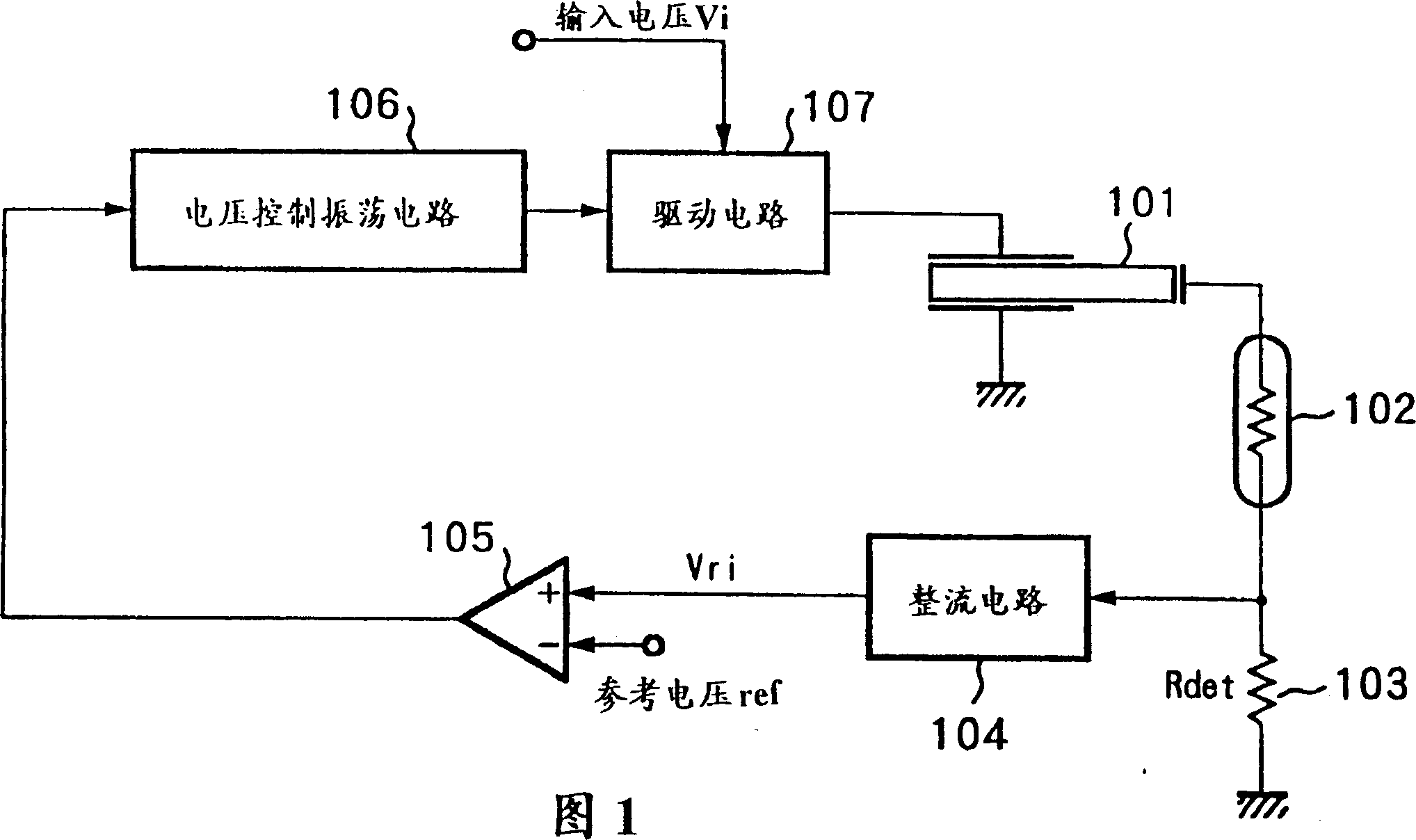
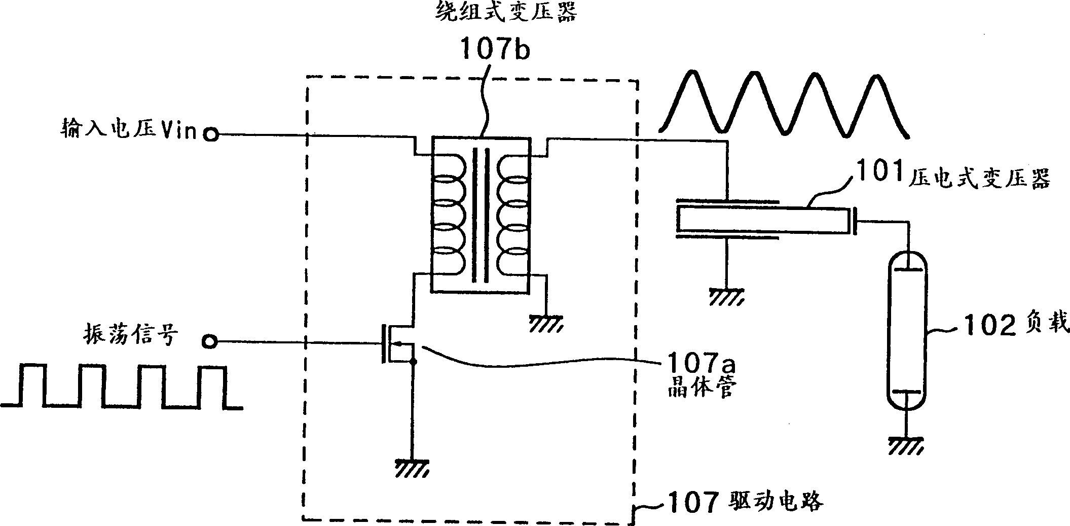
[0096] In Figure 4, reference number 1 represents a piezoelectric transformer; 2 is a load, such as a cold cathode fluorescent lamp connected to the output terminal of the piezoelectric transformer 1, and 3 is a detection resistor Rdet to detect the flow through The current of the load; 4 is a rectifier circuit, used to convert the AC voltage generated in the detection resistor 3 into a DC voltage; 5 is an error amplifier, used to convert the output voltage from the rectifier circuit 4 (load current detection voltage) Vri Compare with a reference voltage Vref1 and amplify its difference; 7 is a drive circuit with and figure 2 The configuration described in the same; 8a and 8b are detection resistors, used to detect the size of the driving voltage delivered to the piezoelectric transformer 1; 9 is a rectifier circuit, used to detect the AC generated in t...
no. 2 example
[0106] The second embodiment will be described below in which the driving circuit 7 is a so-called half-bridge or full-bridge type using switching transistors. Since the configuration of the half-bridge or full-bridge circuit is generally known, its detailed description will be omitted. Figures 7 and 8 schematically show the drive circuit.
[0107] Fig. 7 is a diagram showing the internal configuration of the half-bridge drive circuit of the second embodiment of the present invention.
[0108]In the driving circuit 7A, transistors 7a and 7b, such as FETs (field effect transistors; in this second embodiment, transistors 7a and 7b are p-type and n-type, respectively), are used to form a half-bridge type, such as Shown in Figure 7. Two types of oscillating signals are respectively output from the voltage control oscillation circuit 11A (described later) to the high side and the low side to alternately turn on / off the transistors 7a and 7b. By the switching operation of the driving ci...
no. 3 example
[0129] This third embodiment will be taken as an example of a case where the wide-range brightness control function of the cold cathode fluorescent lamp used as load 2 is added to the piezoelectric transformer control circuit described in the first embodiment.
[0130] Fig. 15 is a block diagram of a piezoelectric transformer control circuit according to a third embodiment of the present invention. In FIG. 15, the same reference numerals as the control circuit in FIG. 4 described in the first embodiment are used to represent the same parts, and the description thereof will be omitted here.
[0131] In FIG. 15, reference number 13 represents a pulse power supply circuit, which can generate a pulse type power supply voltage (hereinafter referred to as pulse voltage) from the input voltage Vi, supply it to the driving circuit 7, and control the pulse voltage The pulse width or period length.
[0132] The driving circuit 7 can output a driving voltage from the pulse voltage of the pul...
PUM
 Abstract
Description
Claims
Application Information
 - R&D
- Intellectual Property
- Life Sciences
- Materials
- Tech Scout
- Unparalleled Data Quality
- Higher Quality Content
- 60% Fewer Hallucinations
Browse by: Latest US Patents, China's latest patents, Technical Efficacy Thesaurus, Application Domain, Technology Topic, Popular Technical Reports.
© 2025 PatSnap. All rights reserved.Legal|Privacy policy|Modern Slavery Act Transparency Statement|Sitemap|About US| Contact US: help@patsnap.com