
Gear heat treatment machining equipment

A technology for processing equipment and gears, which is applied in the field of gear heat treatment processing equipment, and can solve problems such as high-efficiency tempering and quenching, singleness, and reduced efficiency

Active Publication Date: 2020-11-06
嘉兴特威金属科技股份有限公司
View PDF2 Cites 0 Cited by
  • Summary
  • Abstract
  • Description
  • Claims
  • Application Information

AI Technical Summary

Problems solved by technology

[0002] In the process of gear heat treatment, it often involves putting the gears into a high-temperature boiler for heating, and then using the process steps to temper or quench the gears accordingly, which makes the gears put into the high-temperature boiler in batches. It will increase the efficiency to a certain extent, but the method of putting a large number of gears into the boiler in the existing equipment is too single and there is no good technical equipment support, resulting in the need for personnel to put them into the equipment in large quantities many times. Moreover, in the process of high-temperature heating of gears, there is no equipment that can realize multi-angle flipping to efficiently and fully heat the gears, so that the gears cannot be heated well during the processing of the gears and the reliability of the actual use of the equipment is reduced. Due to the existence of the above shortcomings, the reliability and efficiency of the equipment are reduced, and when the equipment is actually used, when the gears are batch-packed and clamped in the external space for tempering and quenching, the structure is too simple to achieve efficient tempering with quenching

Method used


Image

  • Gear heat treatment machining equipment
  • Gear heat treatment machining equipment
  • Gear heat treatment machining equipment

Examples


Embodiment Construction

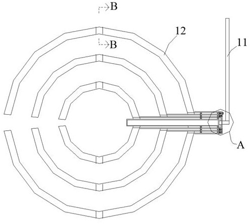
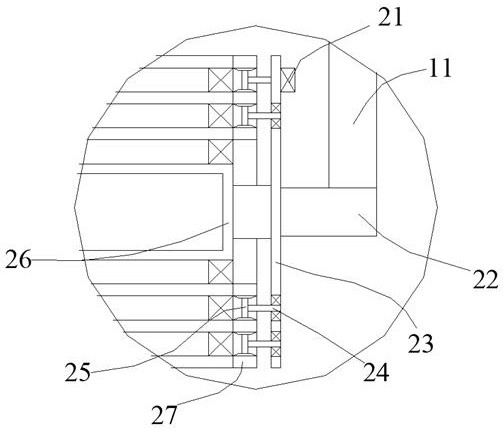
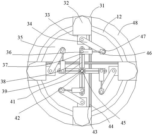
[0022] Such as Figure 1-Figure 3 As shown, the present invention is described in detail. For the convenience of description, the orientations mentioned below are now stipulated as follows: figure 1 The up, down, left, right, front and back directions of the projection relationship are consistent. A gear heat treatment processing equipment of the present invention includes a vertical rod 11, a bottom rod 22 is arranged on the lower side of the vertical rod 11, and a side plate 23 is arranged on one side of the bottom rod 22 One side of the bottom rod 22 is provided with a plurality of outer cylinders 26, and the outer cylinders 26 are stacked with each other. Ring blocks 12 are arranged on one side of the outer cylinders 26 at different positions, and ring blocks 12 are arranged inside the ring blocks 12. Several clamping devices that are convenient for clamping gears of various specifications from the inside. There is a rotation between the ring block 12 and the outer cylinde...


PUM


Abstract

The invention discloses gear heat treatment machining equipment which comprises a vertical rod. A bottom rod is arranged on the lower side of the vertical rod, a side plate is arranged on one side ofthe bottom rod, a plurality of outer cylinders are arranged on one side of the bottom rod, the outer cylinders are arranged in a stacked mode, ring blocks are arranged on one sides of the outer cylinders at different positions, and a plurality of clamping devices which are convenient for clamping gears with various specifications from inside are arranged in the ring blocks. Rotating devices for enabling the outer cylinders at different positions to relatively rotate so as to enable the gears to be fully heated and machined are arranged between the ring blocks and the outer cylinders. The equipment adopts the mode that the gears are fixed on the ring blocks correspondingly, and relative rotation is carried out by the ring blocks to enable the gears to be sufficiently heated and machined.

Description

technical field [0001] The invention relates to the technical field of gear processing equipment, in particular to gear heat treatment processing equipment. Background technique [0002] In the process of gear heat treatment, it often involves putting the gears into a high-temperature boiler for heating, and then using the process steps to temper or quench the gears accordingly, which makes the gears put into the high-temperature boiler in batches. It will increase the efficiency to a certain extent, but the method of putting a large number of gears into the boiler in the existing equipment is too single and there is no good technical equipment support, resulting in the need for personnel to put them into the equipment in large quantities many times. Moreover, in the process of high-temperature heating of gears, there is no equipment that can realize multi-angle flipping to efficiently and fully heat the gears, so that the gears cannot be heated well during the processing of...

Claims


Application Information

Patent Timeline
IPC IPC(8): C21D9/32
CPCC21D9/32C21D9/0025
Inventor 夏江华
Owner 嘉兴特威金属科技股份有限公司
Learn More