Eureka AIR delivers breakthrough ideas for toughest innovation challenges, trusted by R&D personnel around the world.

Seal assembly for compressor

A technology of sealing components and seals, which is applied in the field of compressors and can solve problems such as reducing efficiency and opening gaps

Active Publication Date: 2020-11-06
CARRIER CORP
View PDF9 Cites 0 Cited by
  • Summary
  • Abstract
  • Description
  • Claims
  • Application Information

AI Technical Summary

Problems solved by technology

Opposite moves can open gaps and reduce efficiency

Method used


Image

  • Seal assembly for compressor
  • Seal assembly for compressor
  • Seal assembly for compressor

Examples


Embodiment Construction

[0033] figure 1 A vapor compression system 20 is shown. Exemplary vapor compression system 20 is a refrigerator system. System 20 includes a centrifugal compressor 22 having a suction (inlet) 24 and a discharge (outlet) 26 . The system also includes a first heat exchanger 28 which is a heat rejection heat exchanger (eg, a gas cooler or condenser) in normal operating mode. In the exemplary system, the first heat exchanger 28 is a refrigerant-to-water heat exchanger formed by tube bundles 30, 32 in a condenser unit 34, wherein the refrigerant is cooled by an external water flow. Float valve 36 controls flow from the subcooler chamber surrounding subcooler bundle 32 through the condenser outlet.

[0034] The system also includes a second heat exchanger 38 (in normal mode a heat absorbing heat exchanger or evaporator). In the exemplary system, the second heat exchanger 38 is a refrigerant-to-water heat exchanger formed from a tube bundle 40 for refrigerating the refrigerated w...


PUM


Abstract

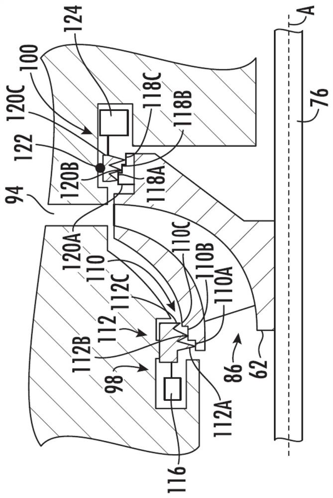
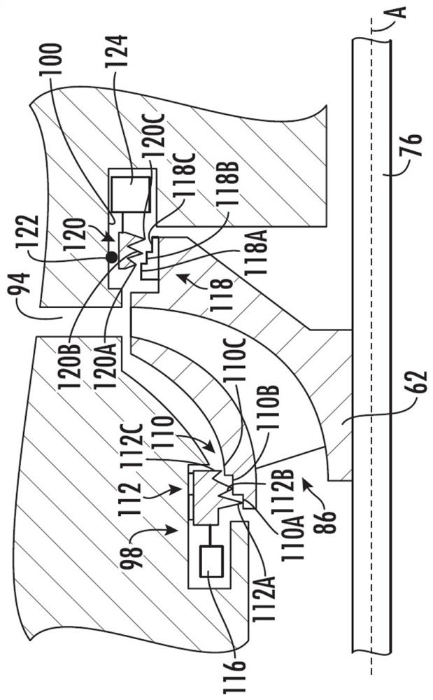
A seal assembly for a compressor includes at least one impeller. At least one seal land is associated with the impeller including a plurality of radially stepped surfaces. A seal is associated with each of at least one seal lands. The seal includes a plurality of radially stepped projections corresponding to the plurality of radially stepped surfaces on at least one seal land. At least one actuator is configured to move at least one seal land relative to the seal.

Description

Background technique [0001] This disclosure relates to compressors. In particular, the present disclosure relates to electric motor driven magnetic bearing compressors. [0002] One particular use for electric motor driven compressors is in liquid refrigerators. An exemplary liquid refrigerator uses a hermetic centrifugal compressor. Exemplary units include individual combinations of compressors, chiller units, refrigerator units, expansion devices, and various additional components. [0003] Some compressors include a transmission interposed between the motor rotor and the impeller to drive the impeller at a faster rotational speed than the motor. In other compressors, the impellers are directly driven by the rotor (eg they are on the same shaft). [0004] Various bearing systems have been used to support compressor shafts. A particular class of compressors uses magnetic bearings (more specifically, electromagnetic bearings). To provide radial support for the shaft, a p...

Claims


Application Information

Patent Timeline
Patent Type & Authority Applications(China)
IPC IPC(8): F04D29/08F04D27/00
CPCF04D29/083F04D27/00F04D29/162F04D29/058F04D17/12F04D27/0246F04D17/122F05B2240/515F05B2240/57F05B2260/507F16J15/445
Inventor V.M.西什特拉
Owner CARRIER CORP
Why Eureka
Eureka Blog
Learn More