
Robot positioning method and device and electronic equipment

A positioning method and robot technology, applied in the field of positioning and navigation, can solve the problem of low robot pose accuracy, and achieve the effect of improving positioning accuracy

Pending Publication Date: 2020-11-06
ゼジャンハーレイテクノロジーカンパニーリミテッド
View PDF13 Cites 17 Cited by
  • Summary
  • Abstract
  • Description
  • Claims
  • Application Information

AI Technical Summary

Problems solved by technology

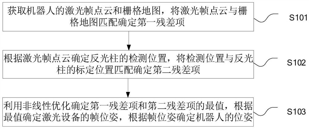
[0005] The embodiment of the present application provides a robot positioning method, device, and electronic equipment, to at least solve the problem of filtering and fusing the contour matching pose and the reflective column matching pose in a filtering-based manner in the related art. When the deviation is large, the pose accuracy of the fusion robot is low

Method used


Image

  • Robot positioning method and device and electronic equipment
  • Robot positioning method and device and electronic equipment
  • Robot positioning method and device and electronic equipment

Examples


Embodiment Construction

[0044] In order to make the purpose, technical solutions and advantages of the present application clearer, the present application will be described and illustrated below in conjunction with the accompanying drawings and embodiments. It should be understood that the specific embodiments described here are only used to explain the present application, and are not intended to limit the present application. Based on the embodiments provided in the present application, all other embodiments obtained by persons of ordinary skill in the art without creative efforts shall fall within the protection scope of the present application.

[0045] Obviously, the accompanying drawings in the following description are only some examples or embodiments of the present application, and those skilled in the art can also apply the present application to other similar scenarios. In addition, it can also be understood that although such development efforts may be complex and lengthy, for those of ...


PUM


Abstract

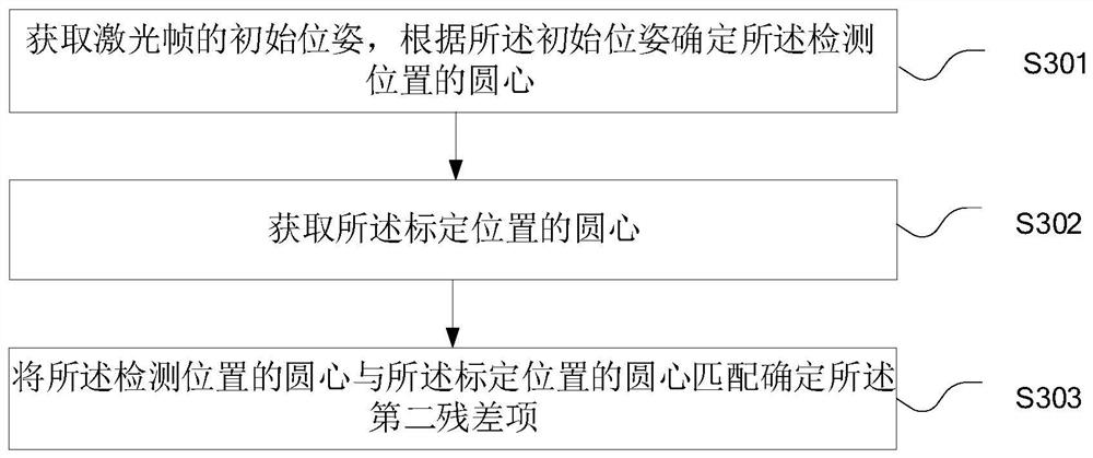
The application relates to a robot positioning method and device and electronic equipment. The method comprises the steps: determining a first residual item through matching of a laser point cloud anda grid map through the obtaining of the laser point cloud and the grid map of a robot; determining a detection position of a reflective column according to the laser point cloud, and matching the detection position with the calibration position of the reflective column to determine a second residual term; determining the maximum and minimum values of the first residual term and the maximum and minimum values of the second residual term by using nonlinear optimization; determining a frame pose of laser equipment according to the maximum and minimum values; and determining the pose of the robotaccording to the frame pose. Therefore, a problem that the pose precision of the robot obtained after fusion is low when the deviation of observation information or prediction information is large due to the fact that filtering fusion is conducted on the pose matched with the contour and the pose matched with the light reflection column based on a filtering mode is solved, and the positioning precision of the robot is improved.

Description

technical field [0001] The present application relates to the technical field of positioning and navigation, in particular to a positioning method, device and electronic equipment for a robot. Background technique [0002] At present, automatic guided transport vehicles are booming, and various guided transport vehicles such as logistics robots, guide robots and home robots have emerged on the market. In the entire robot system, navigation technology is one of its most important core technologies. Navigation technology mainly determines the current pose information of the robot through sensor technology, and clarifies the guidance angle, speed and running route of the car according to the destination information. [0003] In the related technology, the odometer measurement value is used to estimate the pose of the mobile robot in real time during the mapping process. The pose of the robot is calculated by matching the contour with the map during the navigation process, and t...

Claims


Application Information

Patent Timeline
IPC IPC(8): G01C21/00G01C21/20G01S17/86
CPCG01C21/005G01C21/20G01S17/86
Inventor 彭建建林辉卢维殷俊
Owner ゼジャンハーレイテクノロジーカンパニーリミテッド
Learn More