
Patsnap Eureka
For R&D, Patsnap Eureka makes reading and utilizing patents & technical documents easy.
Patsnap Eureka AIR
Designed for self-driven R&D workflows. Generate viable solutions, solve complex R&D challenges, empower your innovation with AI.

Patsnap Eureka Materials
Designed for material experts only. Revolutionize your material R&D, from search, analyze, to developing new materials.

TechResearch
Generate reliable direction feasibility study reports for your R&D in just a few steps.

TechSeek
Discover and master advanced knowledge NOW. Basics, ideas, possibilities, all at once.

TechMind
As an expert in R&D Theories, TechMind can generates customized viable solutions instantly.

TechRisk
Analyze your overall solution with one click, know your potential R&D risks in advance.

TechMonitor
Get weekly tech updates, stay abreast of the latest tech innovations and key insights.
Method for correcting imaging direction of TEM sample
A positive direction, sample technology, applied in the direction of using wave/particle radiation for material analysis, measurement devices, instruments, etc., can solve the problems of low measurement efficiency, measurement error, etc., to facilitate analysis and measurement, reduce inconvenience and Error, avoid the effect of variability
- Summary
- Abstract
- Description
- Claims
- Application Information
AI Technical Summary
Problems solved by technology
Method used
Image

Examples
Embodiment 1
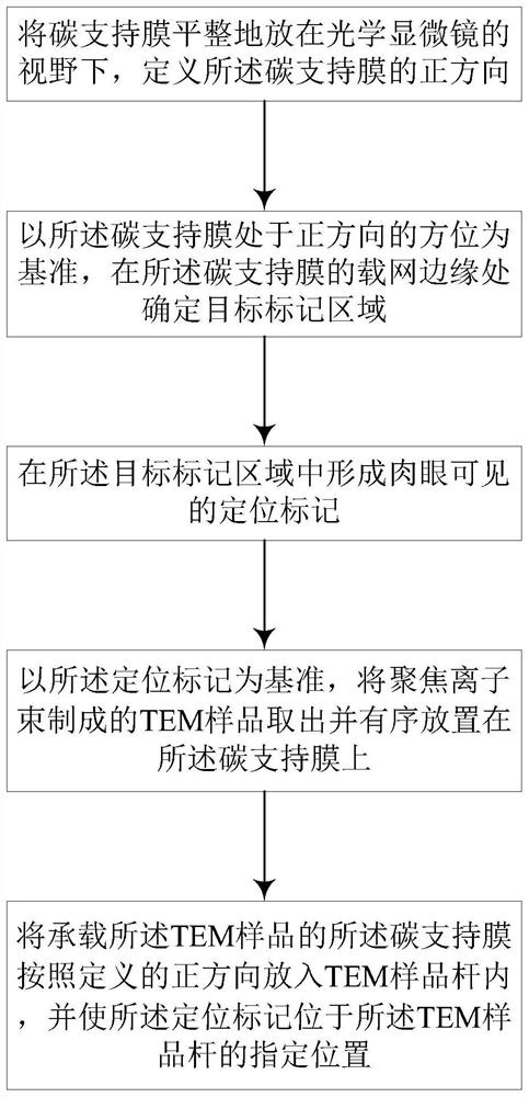
[0040] Methods for correcting the imaging direction of TEM samples, such as image 3 As shown, the specific steps are as follows:
[0041] Step S1, flatly placing the carbon support film under the field of view of an optical microscope (Optical Microscope, OM), and defining the positive direction of the carbon support film;
[0042] Step S2, based on the orientation of the carbon support film in the positive direction, determine the target mark area at the edge of the grid of the carbon support film;
[0043] Step S3, forming a positioning mark visible to the naked eye in the target mark area;
[0044] Step S4, taking out the TEM sample made by the focused ion beam, and placing it on the carbon support film in sequence in a uniform orientation with the positioning mark as a reference;
[0045] Step S5, putting the carbon support film carrying the TEM sample into the TEM sample holder according to the defined positive direction, and making the positioning mark at the designat...
Embodiment 2
[0050] On the basis of the first embodiment, this embodiment further describes the specific implementation of the method for correcting the imaging direction of the TEM sample.
[0051] In this embodiment, the material of the carrier grid in the carbon support film is copper.
[0052] The method for correcting the imaging direction of a TEM sample in this embodiment, the specific steps are as follows:
[0053] Step 1, placing the carbon support film flatly under the field of view of the optical microscope, and defining the positive direction of the carbon support film;
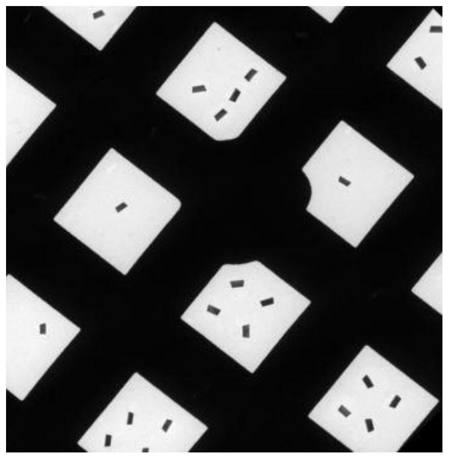
[0054] Such as Figure 4 As shown, the positive direction defined in this embodiment is that the corner of the rectangle is at the bottom right;
[0055] Step 2, based on the orientation of the carbon support film in the positive direction, determine the target mark area at the edge of the grid of the carbon support film;
[0056] Such as Figure 5 As shown, in this embodiment, after defining the positive ...
PUM
| Property | Measurement | Unit |
|---|---|---|
| thickness | aaaaa | aaaaa |
Abstract
Description
Claims
Application Information
 - R&D Engineer
- R&D Manager
- IP Professional
- Industry Leading Data Capabilities
- Powerful AI technology
- Patent DNA Extraction
Browse by: Latest US Patents, China's latest patents, Technical Efficacy Thesaurus, Application Domain, Technology Topic, Popular Technical Reports.
© 2024 PatSnap. All rights reserved.Legal|Privacy policy|Modern Slavery Act Transparency Statement|Sitemap|About US| Contact US: help@patsnap.com