Dies for manufacturing substrates and methods of making

a technology of dies and substrates, applied in the field of die manufacturing processes, can solve the problems of variable increases in slot width, difficult precision alignment of edm electrodes to pre-existing slots, and inability to meet the requirements of edm electrodes,

Inactive Publication Date: 2009-09-03
CORNING INC
View PDF15 Cites 7 Cited by
  • Summary
  • Abstract
  • Description
  • Claims
  • Application Information

AI Technical Summary

Benefits of technology

[0009]The present disclosure provides a die manufacturing process that is economical and avoids the problems of sputter build-up, die variabilities, and attendant material waste. Various methods of manufacturing dies are described, using plunge EDM machining, which produces a consistent and predictable overcut, followed by slot machining, preferably by wire slot machining. Since pre-existing slots are not present before the plunge EDM machining, as in previous approaches, sputter buildup does not occur.

Problems solved by technology

This conventional slot modification method suffers from a number of drawbacks.
Precision alignment of an EDM electrode to a pre-existing slot—such that the XS and IFC modification is centered in the slot—can be difficult due to die and electrode variability.
These variables produce differing amounts of overcut by the EDM machining process, which results in variable increases in slot width.
Slot widths that are greater than or less than targeted design values lead to web width changes in extruded substrates that fail to meet design specifications.
These precision improvements, however, add cost and fabrication time to the die manufacturing process.
Another drawback using conventional methods is “sputter” buildup just below an EDM-modified area.
Since sputter is in the batch flow path, it negatively affects substrate forming during extrusion by producing defects such as missing webs, non-knitters, and the like that cause otherwise good dies to be scrapped, thereby increasing costs.
Dies have also been nickel plated before EDM plunging to act as barrier coating, but the die must be stripped after plunging to remove remnant sputter and nickel, which adds manufacturing steps and increases fabrication complexity.
Slots may also be hand shimmed, which may remove sputter to varying degrees; however, hand shimming is an inexact, labor-intensive process.

Method used


Image

  • Dies for manufacturing substrates and methods of making
  • Dies for manufacturing substrates and methods of making
  • Dies for manufacturing substrates and methods of making

Examples


Embodiment Construction

[0024]The present disclosure will now be described more fully hereinafter with reference to the accompanying drawings in which exemplary embodiments of the disclosure are shown. However, aspects of this disclosure may be embodied in many different forms and should not be construed as limited to the embodiments set forth herein. These exemplary embodiments are provided so that this disclosure will be both thorough and complete, and will fully convey the scope of the disclosure to those skilled in the art. Whenever possible, like reference numerals will be used throughout the detailed description of the disclosure to refer to like or similar elements of the various drawings.

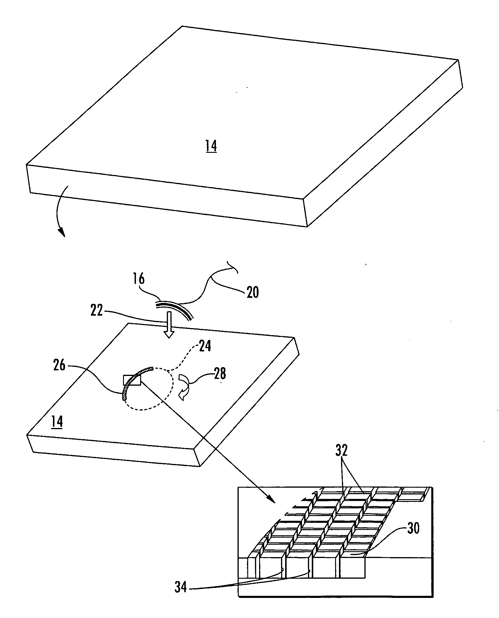
[0025]Turning now to the figures, various embodiments of dies and exemplary methods of manufacturing die pin patterns are shown generally in FIGS. 2-6.

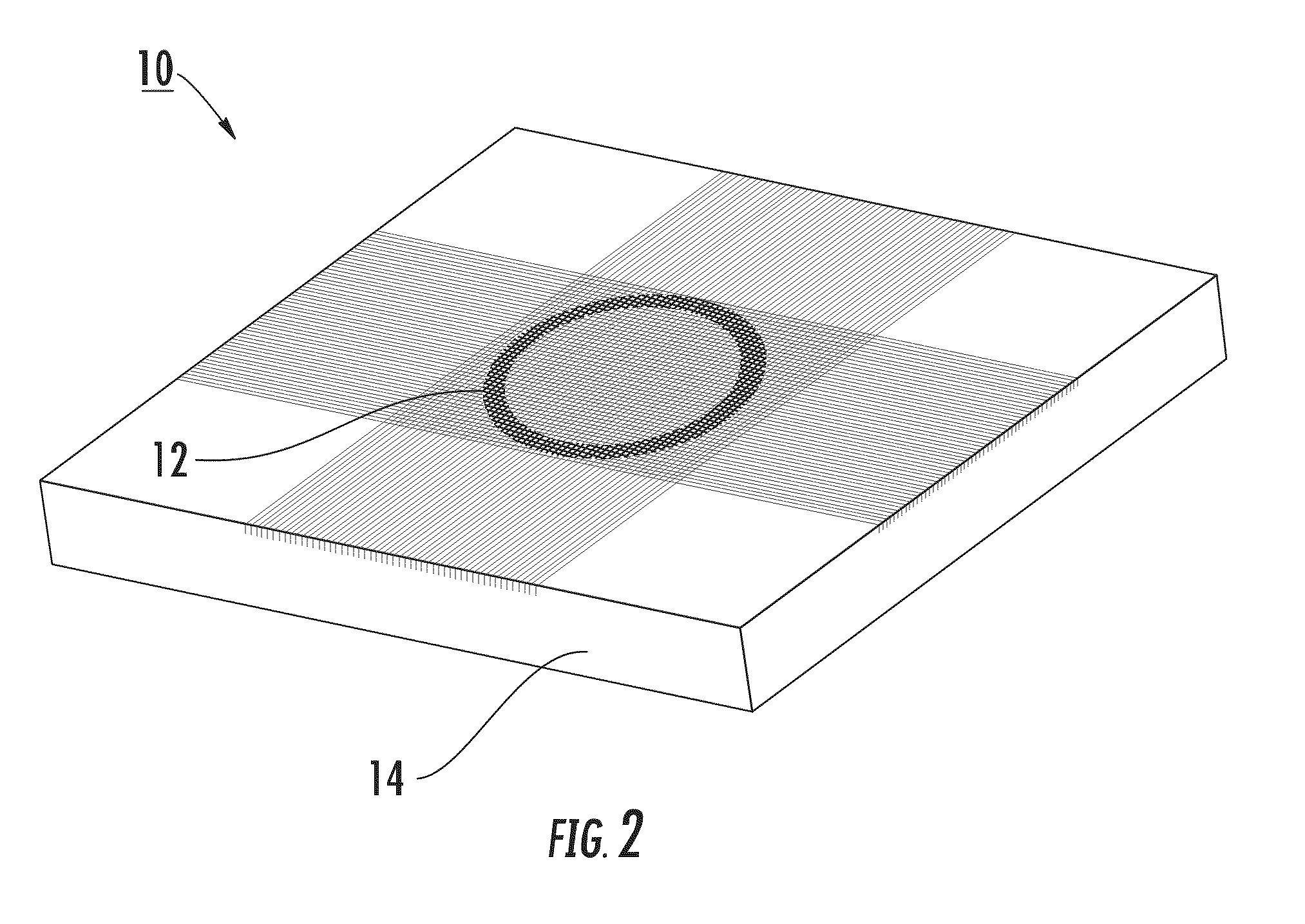
[0026]With particular reference to FIG. 2, a completed die pin fabrication or fabricated die is broadly designated by the element number 10. As shown, a die pin patt...


PUM

PropertyMeasurementUnit
widthaaaaaaaaaa
shapeaaaaaaaaaa
slot widthsaaaaaaaaaa

Abstract

Extrusion dies for manufacturing substrates with peripheral strengthening are manufactured by plunge EDM machining a solid material and subsequently forming slots by wire EDM slot machining.

Description

CROSS-REFERENCE TO RELATED APPLICATIONS[0001]This application claims the benefit of priority under 35 U.S.C. §119(e) of U.S. Provisional Application Ser. No. 61 / 067,393 filed on Feb. 28, 2008.FIELD[0002]The present disclosure relates generally to die manufacturing processes, such as XS or IFC plunge EDM machining followed by wire EDM slot machining.BACKGROUND[0003]Extrusion dies used for manufacturing substrates with peripheral strengthening, such as XS and IFC, are modified by widening pre-existing slots just inside a skinforming region. A spark erosion process known as electrical discharge machining (EDM) is employed using a formed electrode to widen the slots gradually and to radius pin corners in a desired area of a die. This conventional slot modification method suffers from a number of drawbacks.[0004]Precision alignment of an EDM electrode to a pre-existing slot—such that the XS and IFC modification is centered in the slot—can be difficult due to die and electrode variability...

Claims


Application Information

Patent Timeline
Patent Type & Authority Applications(United States)
IPC IPC(8): B23H1/00B29C48/07B29C48/08B29C48/32
CPCB23H9/00B23P15/243B29C47/0028B29C47/003B29L2031/60B29C47/02B29C47/085B29C47/12B29C47/0033B29C48/15B29C48/11B29C48/12B29C48/13B29C48/3001B29C48/07B29C48/08
Inventor FOLMAR, DAVID WILLIAMHUMPHREY, MARK LEESEYLER, SHANE DAVID
Owner CORNING INC
Why Eureka
Try Eureka