Multiple point attachment system for specimen loading or deformation

a multi-point attachment and specimen technology, applied in the direction of measuring devices, scientific instruments, instruments, etc., can solve the problem of not being flexible in the out-of-plane direction, achieve different and controllable tension or compression, avoid unintentional variability, and improve repeatability

Active Publication Date: 2007-08-09
WATERLOO INSTR
View PDF16 Cites 8 Cited by
  • Summary
  • Abstract
  • Description
  • Claims
  • Application Information

AI Technical Summary

Benefits of technology

[0019] The invention provides an integrated specimen attachment system that can be engineered for specific loading conditions. It can be designed to have a different and controllable tension or compression in-axis, off-axis and out-of-plan...

Problems solved by technology

They may or may not be fle...

Method used


Image

  • Multiple point attachment system for specimen loading or deformation
  • Multiple point attachment system for specimen loading or deformation
  • Multiple point attachment system for specimen loading or deformation

Examples


Embodiment Construction

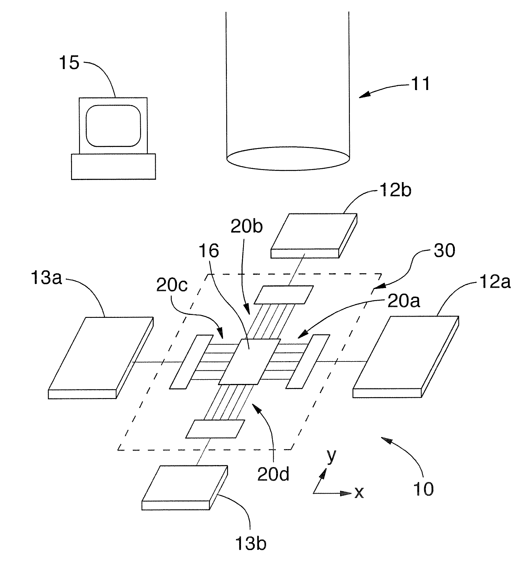
[0053]FIG. 2 shows a complete biaxial load measurement system 10 schematically. A vision system 11 is used to measure the displacement of fiducial markers (not shown in FIG. 2) on the specimen 16 during its initial state and during loading. Fiducial markers may be artificially placed on the test specimen 16 or they may be naturally occurring. A specimen can be almost anything but for this example only, consider the specimen to be a small amount of tissue from a human heart valve 4 mm square. Component 12a provides computer controlled linear motion causing stress [motion] in the X-axis and 12b provides similar stress [motion] in the Y-axis. Components 13a and 13b measure the load in the X and Y directions respectively. The measured stress is readable by the computer 15. The vision system 11, fiducial tracking methods, the loading system 12a and 12b and the load measurement system 13a and 13b are well known in the art and are not part of the invention. They are shown for clarification...


PUM


Abstract

Stresses or deformations can be applied to a specimen, by at least one carrier having a number of flexible fingers extending therefrom, the fingers being securable to the specimen at spaced-apart locations, the carrier typically being attached to a motion-control and load measuring system. The fingers are relatively rigid in tension (or compression if desired) but flexible with respect to motions in other in-plane directions. They may or may not be flexible in out-of-plane directions. Commonly, there may be two carriers on opposite sides of the specimen for applying substantially uniaxial stress, or four carriers at 90 degrees to each other around the specimen for applying substantially biaxial stress, though any number of carriers may be used.

Description

BACKGROUND OF THE INVENTION [0001] 1. Field of the Invention [0002] This invention relates to multiple point attachment to specimens, for biaxial or uniaxial loading, deformation or testing. [0003] Situations exist where it desirable to induce specified loads, deformations or strain states in materials, specimens or objects or to restrain them against motions that would otherwise occur. These include situations where mechanical properties are determined by applying particular loads or combinations of loads in different directions or loading in one direction with or without restraint in another. Other situations include, but are not limited to, manufacturing processes, pre-conditioning of materials, use of stress or strain states to induce fiber alignment, crystallization in the material or situations where it is desired to otherwise regulate, alter or transform the material's properties or structure at the bulk, meso, micro or nano scale. [0004] Attachment to the specimen is often o...

Claims


Application Information

Patent Timeline
IPC IPC(8): G01N3/20
CPCG01N2203/0254G01N3/04
Inventor BRODLAND, G. WAYNE
Owner WATERLOO INSTR
Why Eureka
Try Eureka