
Signal transmitting type base station

A technology for transmitting signals and base stations, which is applied in the field of transmitting signal base stations, and can solve the problems that mobile phone signals cannot be transmitted, complex structures, and falling off

Pending Publication Date: 2020-11-06
重庆桦秀科技有限公司
View PDF0 Cites 0 Cited by
  • Summary
  • Abstract
  • Description
  • Claims
  • Application Information

AI Technical Summary

Problems solved by technology

[0002] As we all know, with the popularization of information technology, various types of communication base stations are used more and more widely. Where signals are needed, base stations are needed to receive and send signals, which facilitates the flow of information for modern humans, especially in many remote areas. Due to the harsh geographical environment, mobile phone signals cannot be sent out, and people can only use mobile phone communications by receiving satellite signals, which requires the use of signal-emitting base stations, but the existing signal-emitting base stations have low security performance. The overall structural strength is insufficient, the installation and disassembly are more troublesome, and the signal transmission is not stable enough, which will bring losses to the user; in addition, the following shortcomings often occur during use; (1) Lack of simultaneous horizontal and pitch rotation, or the process of realizing the rotation The complex structure directly leads to high energy consumption; (2) The position of the gear is unreasonable during the rotation process, and it will fall off over time, resulting in a loss of control of the communication system; (3) The rotating seat is not firm and is easily damaged

Method used

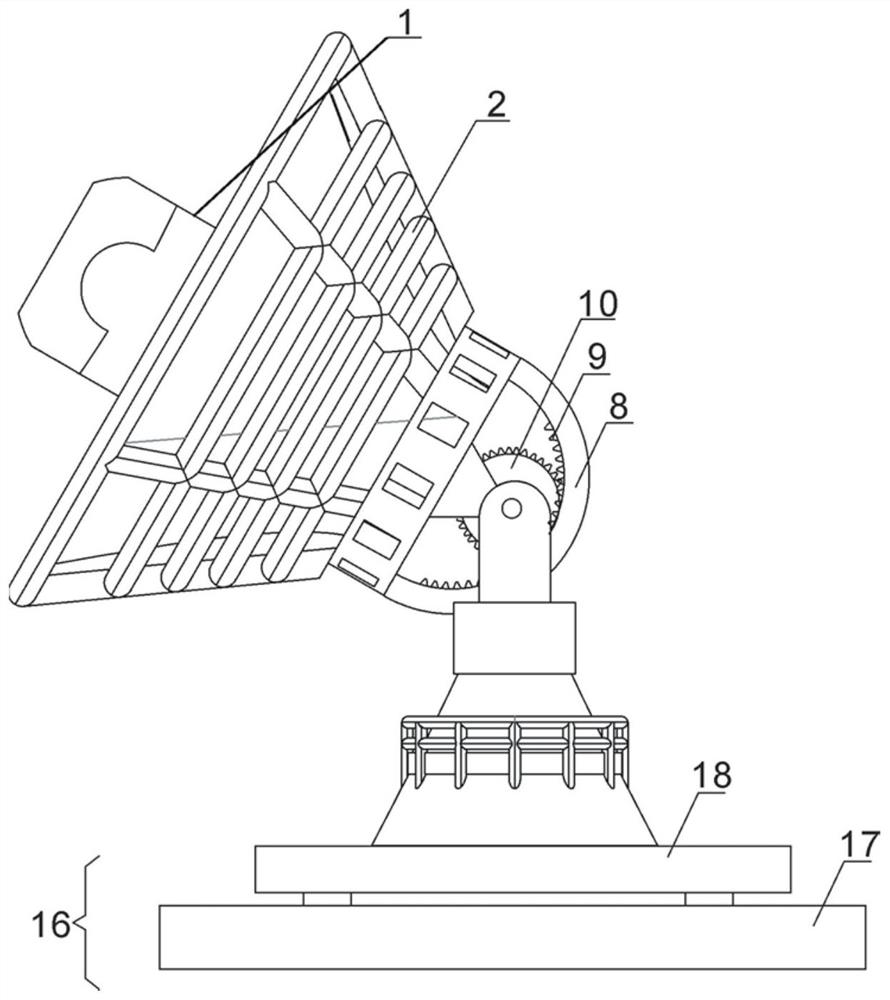
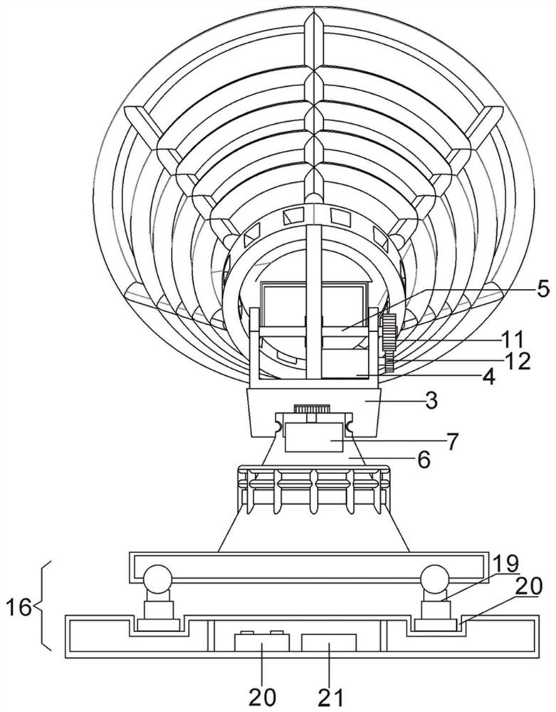
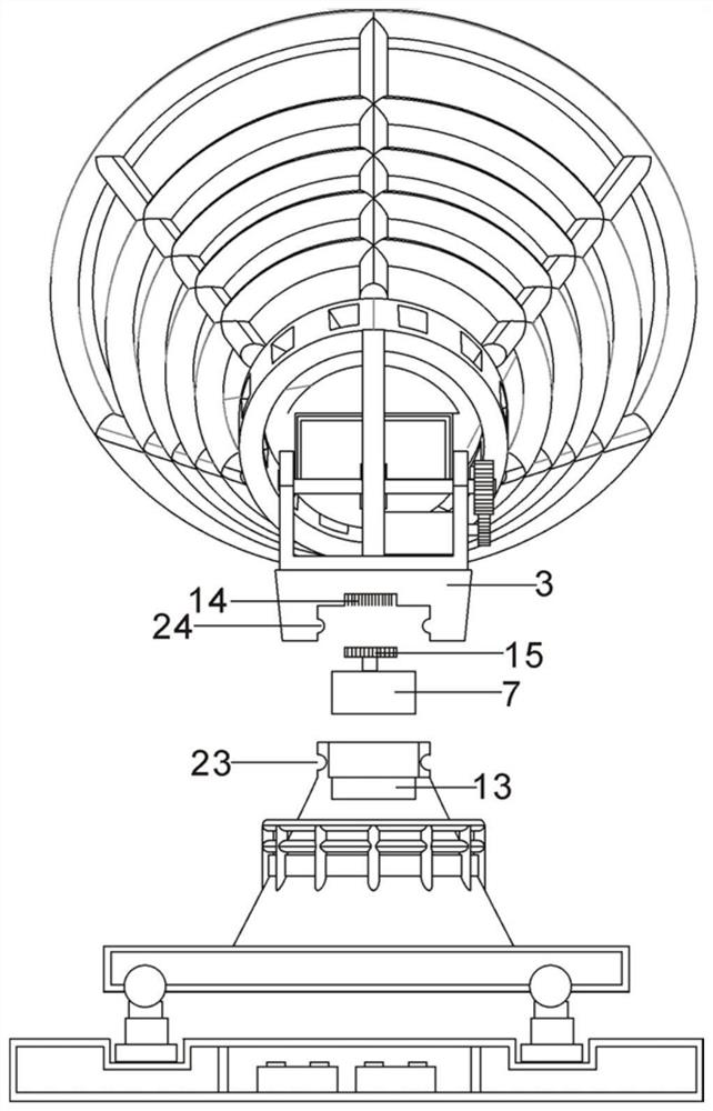

Image

  • Signal transmitting type base station
  • Signal transmitting type base station
  • Signal transmitting type base station

Examples


Embodiment Construction

[0014] The following will be combined with Figure 1-Figure 4 The present invention is described in detail, and the technical solutions in the embodiments of the present invention are clearly and completely described. Apparently, the described embodiments are only some of the embodiments of the present invention, not all of them. Based on the embodiments of the present invention, all other embodiments obtained by persons of ordinary skill in the art without making creative efforts belong to the protection scope of the present invention.

[0015] Embodiment; The present invention provides a signal-emitting base station through improvement, such as Figure 1-Figure 4 As shown, it can be implemented in the following manner; including a carrier frame 2 for connecting the signal transmitting antenna 1, an upper rotating base 3, a pitch adjustment motor 4, a pitch adjustment rotating rod 5, a lower support base 6, a horizontal rotation motor 7 and a machine room 25. The tail of the b...


PUM


Abstract

The invention discloses a signal transmitting type base station. When the signal transmitting type base station is used, a signal transmitting antenna can be driven to rotate horizontally and vertically; the implementation process of pitching rotation is as follows. A pitching adjusting motor is controlled to rotate, then a pitching adjusting rotating rod is driven to rotate through a lower transmission gear and an upper transmission gear, and the pitching adjusting gear drives a bearing frame to do pitching rotation through the inner edge of a tooth section. The realization process of horizontal rotation is as follows. The horizontal rotating motor is controlled to rotate, the rotating gear drives a hole cavity to achieve transmission, and therefore the upper rotating base is driven to integrally rotate, and horizontal steering of the bearing frame is achieved. The base station is simple in structure, the structure of an existing device is changed, and excessive transmission connection and energy consumption are avoided. In addition, a machine room is integrated in the base station, so that the base station can be conveniently installed by operators and operated by workers under the condition that the occupied space is reduced, and signals can be transmitted through the arranged signal transmitting antenna.

Description

technical field [0001] The present invention relates to the field of signal base stations, in particular to a signal-emitting base station. Background technique [0002] As we all know, with the popularization of information technology, various types of communication base stations are used more and more widely. Where signals are needed, base stations are needed to receive and send signals, which facilitates the flow of information for modern humans, especially in many remote areas. Due to the harsh geographical environment, mobile phone signals cannot be sent out, and people can only use mobile phone communications by receiving satellite signals, which requires the use of signal-emitting base stations, but the existing signal-emitting base stations have low security performance. The overall structural strength is insufficient, the installation and disassembly are more troublesome, and the signal transmission is not stable enough, which will bring losses to the user; in addit...

Claims


Application Information

Patent Timeline
IPC IPC(8): H04B1/03H04B1/04H04W88/08
CPCH04B1/03H04B1/04H04W88/08
Inventor 郑颖
Owner 重庆桦秀科技有限公司
Learn More