
Laser-based space optical communication device

A space optical communication and laser technology, applied in free space transmission and other directions, can solve the problems of occupying radio frequency resources, not very strong anti-interference ability, and high information security requirements, achieving easy use, easy laser alignment, and electromagnetic compatibility. good effect

Inactive Publication Date: 2020-11-06
中达安(福建)科技有限公司
View PDF5 Cites 1 Cited by
  • Summary
  • Abstract
  • Description
  • Claims
  • Application Information

AI Technical Summary

Problems solved by technology

[0005] For this reason, it is necessary to provide a laser-based spatial optical communication device to solve the problem of places with high requirements for information confidentiality. Wireless communication is used in the one-way data transmission process, which occupies radio frequency resources, and the anti-interference ability is not very good. Strong, poor confidentiality and other issues

Method used


Image

  • Laser-based space optical communication device
  • Laser-based space optical communication device
  • Laser-based space optical communication device

Examples


specific Embodiment approach

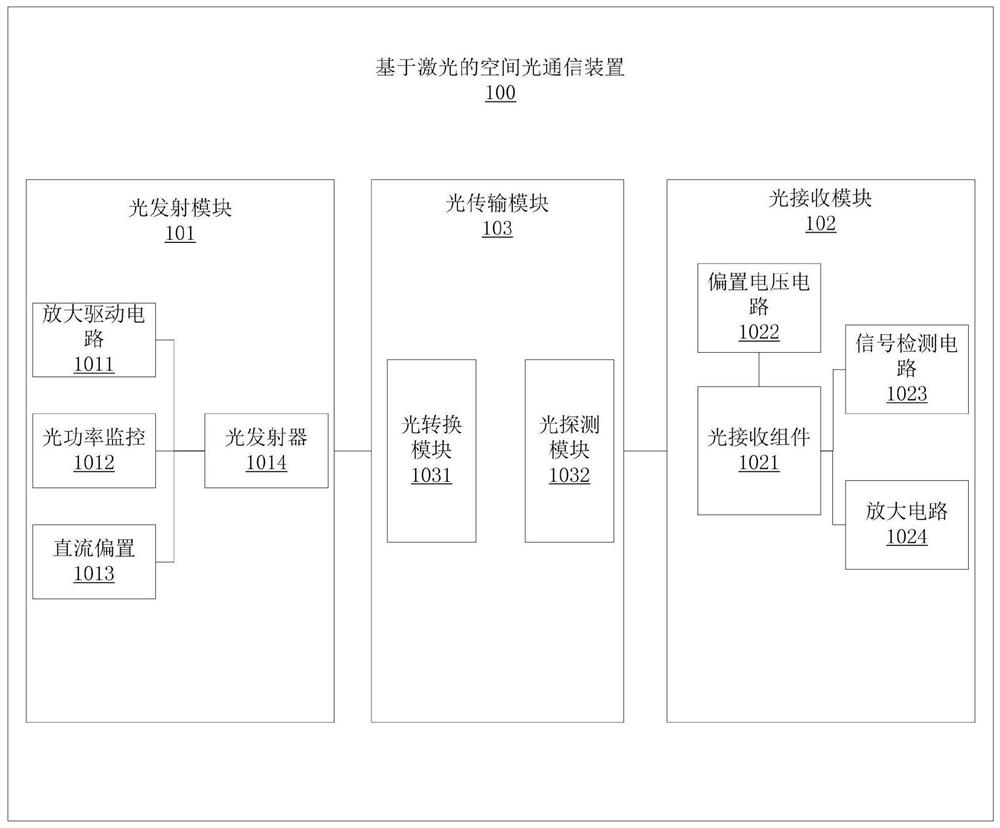
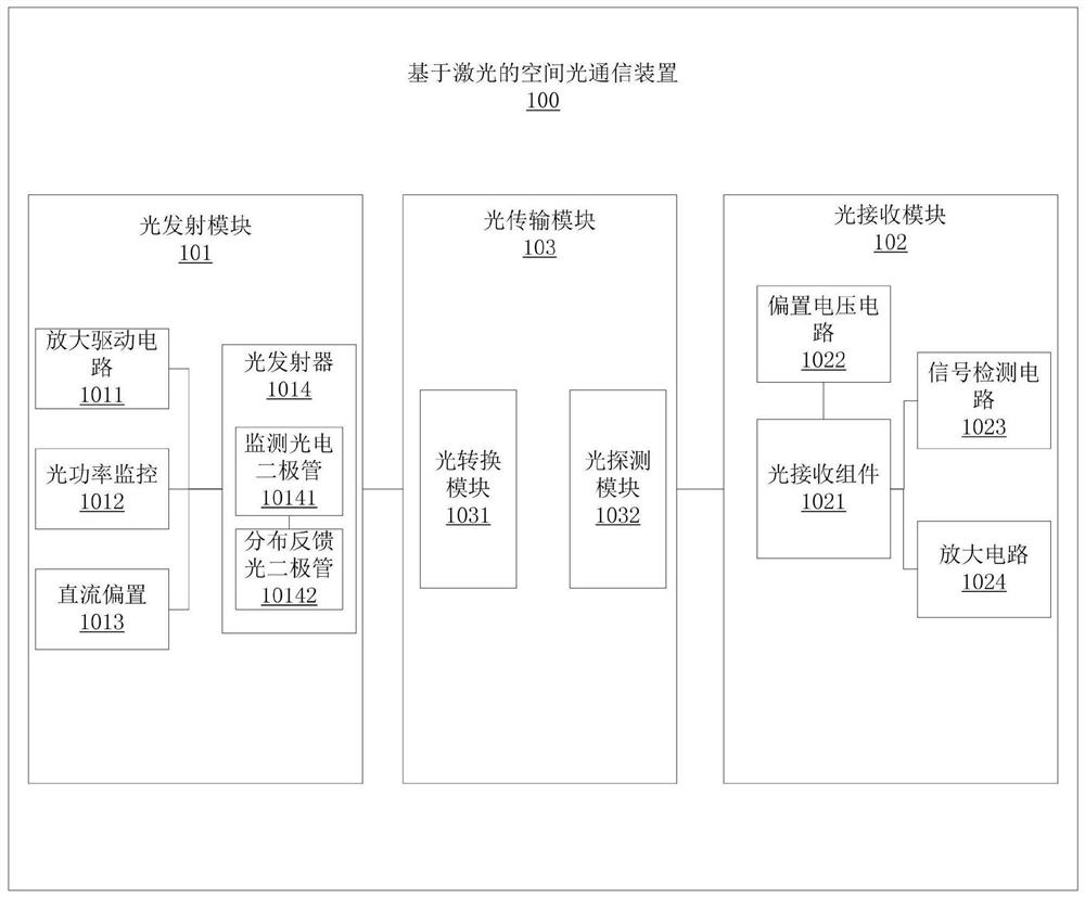
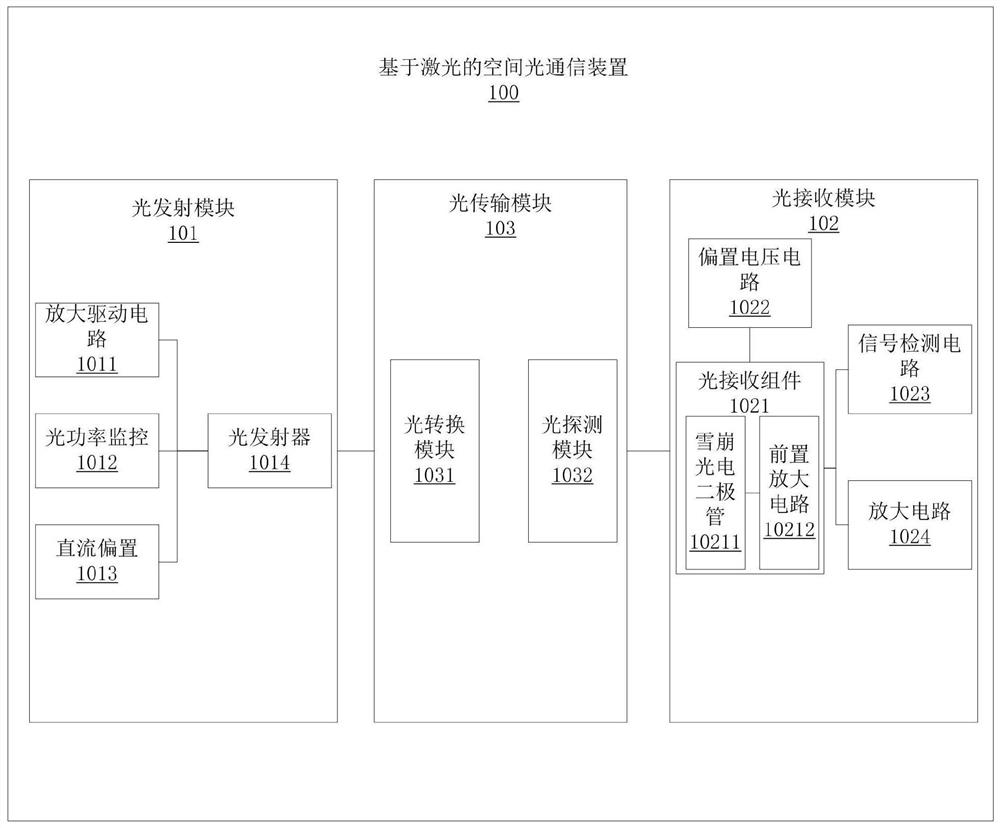
[0046] see Figure 1 to Figure 3 , in this embodiment, a specific implementation of a laser-based spatial optical communication device 100 is as follows:

[0047] A laser-based spatial optical communication device 100, comprising: an optical transmitting module 101, an optical receiving module 103, and an optical transmission module 102;

[0048] The optical transmission module 102 is respectively connected to the optical transmitting module 101 and the optical receiving module 103;

[0049] The optical transmitting module 101 includes: an amplification drive circuit 1011, an optical power monitoring 1012, a DC bias 1013 and an optical transmitter 1014;

[0050] The optical transmitter 1014 is respectively connected to the amplification drive circuit 1011, the optical power monitoring 1012 and the DC bias 1013;

[0051] The amplifying drive circuit 1011 is used for: receiving a radio frequency signal, and the optical transmitter 1014 is used for: emitting an optical signal; ...


PUM

PropertyMeasurementUnit
Wavelengthaaaaaaaaaa

Abstract

The invention relates to the field of spatial light transmission equipment, in particular to a laser-based space optical communication device. The laser-based space optical communication device comprises a light emission module, a light receiving module and a light transmission module, the light emission module comprises an amplification driving circuit, a light power monitor, a direct current bias and a light emitter. The light emitter is connected with the amplification driving circuit, the light power monitor and the direct current bias; the light transmission module comprises an optical conversion module and an optical detection module. The light receiving module comprises a light receiving assembly, a bias voltage circuit, a signal detection circuit and an amplification circuit. Thelight receiving assembly is connected with the bias voltage circuit, the signal detection circuit and the amplification circuit. Due to the fact that the one-way transmission performance of the laseris visual and visible, no hidden reverse link exists, and due to the fact that a laser is good in electromagnetic compatibility, high in strong electromagnetic interference resistance and the like, the spatial light communication module based on the laser has very high safety.

Description

technical field [0001] The invention relates to the field of spatial optical transmission equipment, in particular to a laser-based spatial optical communication device. Background technique [0002] With the development of science and technology, the increase in the amount of information, the implementation of the national big data strategy, the continuous expansion of data transmission requirements and application scope, network information security issues have received extensive attention. For this reason, many government agencies, military units, and companies have strengthened their efforts. Security and confidentiality measures for internal information systems. One of the important measures is to implement complete physical isolation between the internal information system and the external network. In order to prevent ferry attacks and stealing secrets, many units prohibit mobile carriers from transmitting information between external network and internal network comp...

Claims


Application Information

Patent Timeline
IPC IPC(8): H04B10/11
CPCH04B10/11
Inventor 林征宇许成功庄文付军朱瑞亮
Owner 中达安(福建)科技有限公司
Learn More