The baffle structure of the pipe expander
A technology of baffle structure and pipe expander, which is applied in the direction of storage devices, metal processing equipment, feeding devices, etc., can solve the problems of time-consuming and laborious, low clamping efficiency, and manual positioning of baffles, so as to reduce processing procedures, Improve production efficiency, convenient and fast clamping effect
- Summary
- Abstract
- Description
- Claims
- Application Information
AI Technical Summary
Problems solved by technology
Method used
Image

Examples
Embodiment 1
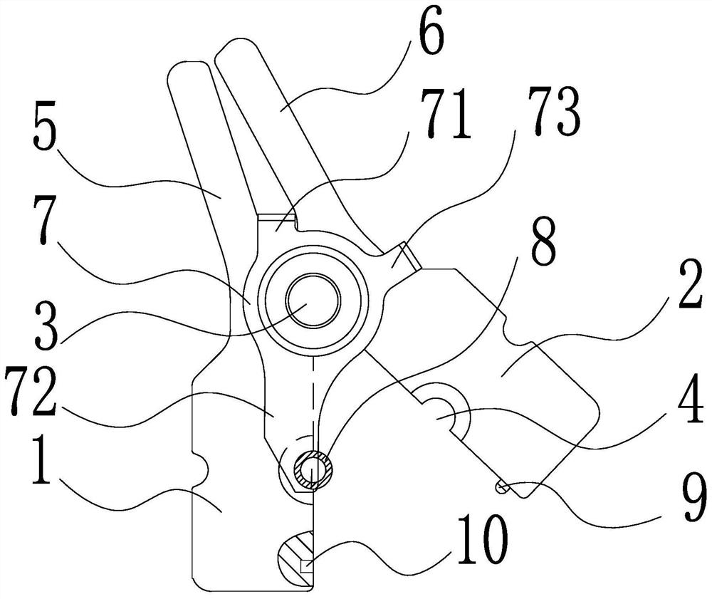
[0024] Such as figure 1 and figure 2 As shown, the baffle plate structure of a pipe expander of the present invention includes a left chuck 1 and a right chuck 2 that are rotatably connected to the rotating shaft 3, and the corresponding left chuck 1 and right chuck 2 on the lower side of the rotating shaft 3 are closed. Finally, it forms a cuboid shape, and the matching surfaces of the two are jointly enclosed to form a circular jaw 4. The jaws 4 are symmetrically distributed on the left and right relative to the mating surface. The left chuck 1 and the right chuck corresponding to the upper side of the rotating shaft 3 The head 2 forms a left force application handle 5 and a right force application handle 6, and the left force application handle 5 and the right force application handle 6 are also symmetrically distributed on the left and right relative to the mating surface, on the corresponding rotating shaft 3 outside the inner port of the jaw 4 The coaxial rotation is c...
Embodiment 2
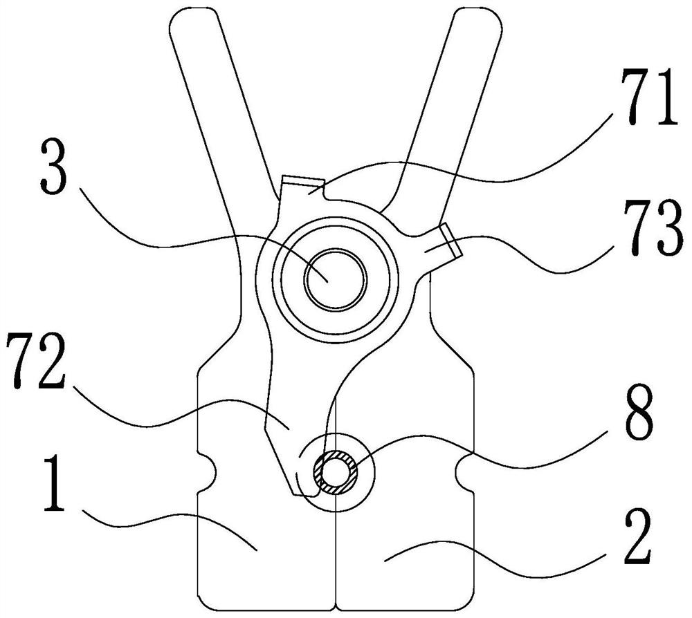
[0027] Such as Figure 5 As shown, the reset hanging plate 73 is integrally connected to the "one"-shaped member on the baffle plate 7, and the outer end of the reset hanging plate 73 extends to the outside of the surface of the right chuck 2 near the jaw 4 (two sides of the jaw 4). The left collet 1 and the right collet 2 corresponding to the side are mutually matched with the inner wall of the pipe expander on the pipe expander), the angle between the reset hanging plate 73 and the pipe fitting end face positioning plate 72 in this embodiment is less than 90°, and The outer end of the reset hanging plate 73 is arc-shaped (to reduce the friction force between it and the inner wall of the expansion chamber), and when the chuck after the clamping pipe fitting 8 is sent into the expansion chamber, the expansion chamber matched with it will The inner wall surface, that is, the overhead reset hanging plate 73 rotates clockwise downward around the rotating shaft 3, thereby driving ...
Embodiment 3
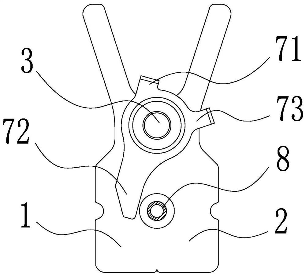
[0029] Such as Figure 6 and Figure 7 As shown, the reset hanging plate 73 is integrally connected to the "one"-shaped member on the baffle plate 7, and the outer end of the reset hanging plate 73 extends to the outside of the surface of the right chuck 2 near the jaw 4 (two sides of the jaw 4). The left collet 1 and the right collet 2 corresponding to the side are mutually matched with the inner wall of the pipe expander on the pipe expander), and the included angle between the reset hanging plate 73 and the positioning plate 72 on the end face of the pipe fitting is ≥90° (two in this embodiment or close to 90°), when the chuck with the pipe fitting 8 clamped is sent into the expansion chamber for chuck clamping, the outer end of the reset hanging plate 73 is hooked on the edge of the expansion chamber port, so that the end surface of the pipe fitting is positioned The plate 72 rotates counterclockwise around the rotating shaft 3 and leaves the port of the jaw 4 . All the ...
PUM
 Abstract
Description
Claims
Application Information
 - R&D Engineer
- R&D Manager
- IP Professional
- Industry Leading Data Capabilities
- Powerful AI technology
- Patent DNA Extraction
Browse by: Latest US Patents, China's latest patents, Technical Efficacy Thesaurus, Application Domain, Technology Topic.
© 2024 PatSnap. All rights reserved.Legal|Privacy policy|Modern Slavery Act Transparency Statement|Sitemap