Execution joint integrated structure for exoskeleton robot joints

An exoskeleton robot and joint technology, applied in the field of robotics, can solve problems such as affecting joint motion performance and accuracy, low degree of practicality, joint output torque and real-time response decline, etc., to avoid multi-line wear and mutual interference, improve Reliability and availability, the effect of reducing size and mass

Pending Publication Date: 2020-11-10
THE 21TH RES INST OF CHINA ELECTRONIC TECH GRP CORP
View PDF0 Cites 4 Cited by
  • Summary
  • Abstract
  • Description
  • Claims
  • Application Information

AI Technical Summary

Problems solved by technology

[0003] The joint execution structure of traditional exoskeleton robots is mainly composed of a single motor and reducer integrated structure, hydraulic structure, and ball screw structure. The decline in torque and real-time response directly affects the performance and accuracy of joint motion, and directly affects the performance and maturity of exoskeleton robots.
[0004] At present, there are integrated machines integrating motor and harmonic reducer, and integrated machines integrating motor, harmonic reducer and driver. They are simple integrated execution joints designed for industrial robots or collaborative robots. They can be used in To a certain extent, the integration of joints can be improved, but it cannot be applied to the special execution joint parts of exoskeleton robots, and the above integrated joints have the following di

Method used


Image

  • Execution joint integrated structure for exoskeleton robot joints
  • Execution joint integrated structure for exoskeleton robot joints
  • Execution joint integrated structure for exoskeleton robot joints

Examples


Embodiment Construction

[0029] The present invention will be described in detail below with reference to the accompanying drawings and examples. Each example is provided by way of explanation of the invention, not limitation of the invention. In fact, those skilled in the art will recognize that modifications and variations can be made in the present invention without departing from the scope or spirit of the invention. For example, features illustrated or described as part of one embodiment can be used on another embodiment to yield a still further embodiment. Therefore, it is intended that the present invention includes such modifications and variations as come within the scope of the appended claims and their equivalents.

[0030] In the description of the present invention, the terms "longitudinal", "transverse", "upper", "lower", "front", "rear", "left", "right", "vertical", "horizontal", " The orientations or positional relationships indicated by "top", "bottom", etc. are based on the orienta...


PUM


Abstract

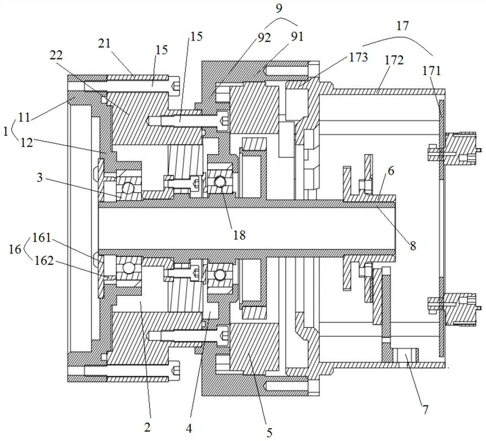
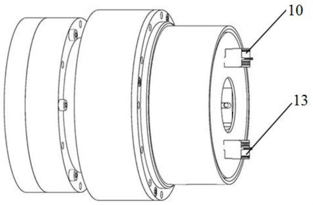
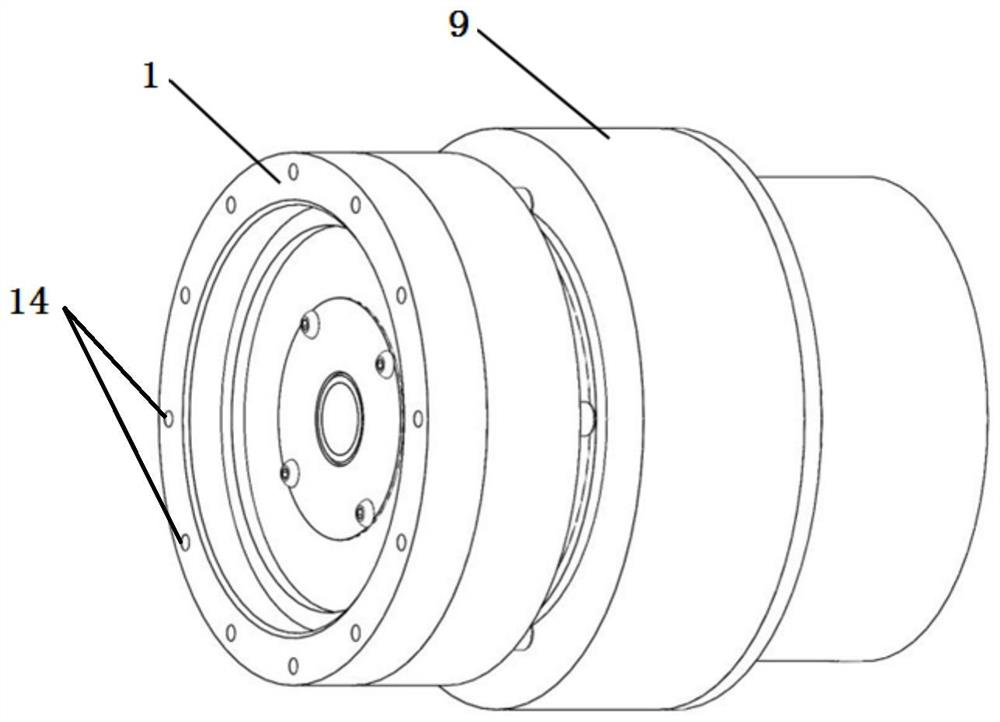
The invention belongs to the technical field of robots, and relates to an execution joint integrated structure for exoskeleton robot joints. The structure comprises a motor, wherein the motor is provided with a rotating shaft and a motor shell, and the motor shell is provided with a motor front end cover and a motor rear end cover connected with one end of the motor front end cover; a brake, wherein the brake is provided with a brake disc and a friction member, the brake disc is connected to the rotating shaft in a sleeving manner, and the friction member is arranged at the other end of the motor front end cover and used for braking the brake disc; a harmonic speed reducer, wherein the harmonic speed reducer is arranged on the rotating shaft and provided with a steel wheel, the steel wheelis provided with a fixing portion and an output portion rotationally arranged on the radial outer side of the fixing portion, the fixing portion is connected with the other end of the motor front endcover, and the harmonic speed reducer and the friction member are further arranged on the two sides of the brake disc separately; and an output end cover, wherein the output end cover is connected with the output portion and further connected with the exoskeleton robot joints. The rotating shaft is rotationally arranged in an outer shell formed by the motor shell, the steel wheel and the output end cover. By means of the scheme, the compactness of the structure is improved, and the size is reduced.

Description

technical field [0001] The invention belongs to the technical field of robots, and in particular relates to an integrated structure of an executive joint for an exoskeleton robot joint. Background technique [0002] It is of great value and revolutionary significance to implement the joint-integrated structure in the joints of exoskeleton machines. It brings problems of poor stability, large volume, large mass and large inertia to the long-term use of reducers, motors and brakes for single installation combination and separation of drive and control. , These problems have always been the key technical issues that need to be solved for the joints of exoskeleton robots. The solution of the problems is of great significance to the improvement of the performance, practicality and industrialization of exoskeleton robots. [0003] The joint execution structure of traditional exoskeleton robots is mainly composed of a single motor and reducer integrated structure, hydraulic structu...

Claims


Application Information

Patent Timeline
IPC IPC(8): B25J17/02B25J9/00
CPCB25J9/0006B25J17/02
Inventor 何洪军袁德宇高哲方略
Owner THE 21TH RES INST OF CHINA ELECTRONIC TECH GRP CORP
Why Eureka
Try Eureka