Dicing device for boards with different lengths

A technology of different lengths and dicing, applied in feeding devices, clamping devices, charging devices, etc., to reduce labor intensity

Inactive Publication Date: 2020-11-10
赵三秀
View PDF10 Cites 6 Cited by
  • Summary
  • Abstract
  • Description
  • Claims
  • Application Information

AI Technical Summary

Problems solved by technology

[0005] In order to overcome the disadvantage of manually pushing wood boards of different lengths to cut into pieces, the technical problem to be solved by the invention is to provide a cutting device for wood boards of different lengths that does not need to be manually pushed to cut wood boards of different lengths

Method used


Image

  • Dicing device for boards with different lengths
  • Dicing device for boards with different lengths
  • Dicing device for boards with different lengths

Examples


Embodiment 1

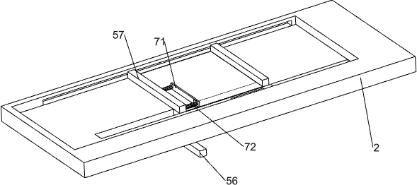
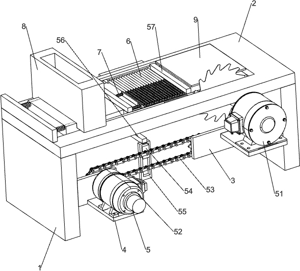
[0027] A cutting device for planks of different lengths, such as Figure 1-3 , Figure 5 and Figure 8 As shown, it includes a support plate 1, a mounting plate 2, a first connecting plate 3, a storage plate 4 and a cutting mechanism 5, the left and right sides of the bottom of the mounting plate 2 are connected with the support plate 1, and the left side of the right support plate 1 A first connection plate 3 is connected to the surface, and a storage plate 4 is connected to the right side of the left support plate 1 , and a cutting mechanism 5 is installed between the storage plate 4 and the first connection plate 3 .

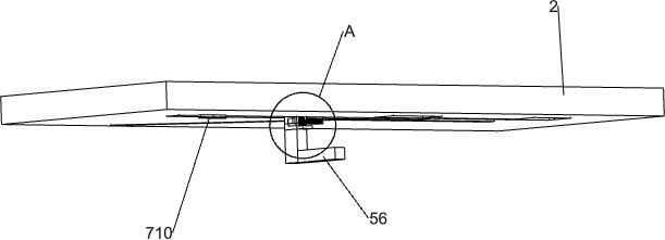
[0028] The block cutting mechanism 5 includes a cutting machine 51, a servo motor 52, a transmission chain group 53, a first slider 54, a first transmission plate 55, a first L-shaped connecting plate 56 and a material delivery frame 57, and the front of the first connecting plate 3 The cutting machine 51 is installed at the top, the mounting plate 2 on the...

Embodiment 2

[0031] On the basis of Example 1, such as Figure 1-4 and Figure 8 As shown, a screening mechanism 6 is also included. The screening mechanism 6 includes a slide plate 61, a rod sleeve 62, a return spring 63, a second connecting plate 64, a second sliding block 65 and a push rod 66. There is a guide groove at the bottom of the mounting plate 2 67, the second slider 65 is slidingly connected in the guide groove 67, the bottom of the second slider 65 is connected with the second connecting plate 64, the rear side of the second connecting plate 64 is connected with a sliding plate 61, and the sliding plate 61 slides with the mounting plate 2 The slide plate 61 is in contact with the delivery frame 57. A plurality of rod sleeves 62 are evenly spaced on the top of the slide plate 61. The rod sleeve 62 is slidingly connected with a push rod 66. The front portion of the push rod 66 is connected to the front end of the rod sleeve 62. A return spring 63 is connected between them.

...

Embodiment 3

[0034] On the basis of Example 2, such as Figure 5-7As shown, a clamping mechanism 7 is also included, and the clamping mechanism 7 includes a splint 71, a first spring 72, a second L-shaped connecting plate 73, a first rack 74, a first transmission rod 75, a one-way gear 76, The bevel gear 77, the second transmission rod 78, the second gear 79 and the second rack 710, the inner surface on the left side of the delivery frame 57 are connected with two first springs 72, and the right ends of the two first springs 72 are connected to each other. Clamping plate 71 is arranged, and the first L-shaped connecting plate 56 top is slidably connected with the second L-shaped connecting plate 73, and the second L-shaped connecting plate 73 is slidably connected with the delivery frame 57, and the top of the second L-shaped connecting plate 73 is connected with the clamping plate. 71 is connected at the bottom, the front side of the second L-shaped connecting plate 73 is connected with t...


PUM


Abstract

The invention relates to a dicing device, in particular to a dicing device for boards with different lengths. According to the dicing device for the boards with the different lengths, the boards withthe different lengths do not need to be manually pushed to be diced. The dicing device for the boards with the different lengths comprises a mounting plate, a first connecting plate, a storage plate and a dicing mechanism; supporting plates connected to the two sides of the bottom of the mounting plate; one of the supporting plates is connected with the first connecting plate; the other supportingplate is connected with the storage plate; and the dicing mechanism is mounted between the storage plate and the first connecting plate. According to the dicing device, the dicing mechanism and a screening mechanism are matched to push the boards with the different lengths to be diced, so that the boards with the different lengths do not need to be manually pushed to be diced, and the labor intensity of workers can be reduced.

Description

technical field [0001] The invention relates to a cutting device, in particular to a cutting device for planks with different lengths. Background technique [0002] At present, cutting boards of different lengths is generally performed manually. When manually cutting boards of different lengths, stack more boards of different lengths in order, and then manually push more boards of different lengths to the cutting machine. Moving in the same direction, the planks with different lengths are cut into pieces by a cutting machine, so it is necessary to manually push and move the planks with different lengths manually, so that the labor intensity of the workers is relatively high. [0003] Therefore urgently need to develop a kind of cutting device for planks with different lengths that does not need to manually push planks with different lengths for cutting. Contents of the invention [0004] (1) Technical problems to be solved [0005] In order to overcome the shortcoming of...

Claims


Application Information

Patent Timeline
Patent Type & Authority Applications(China)
IPC IPC(8): B27B5/06B27B5/22B27B5/29B27B25/00B27B25/06B27B29/02B27B31/02
CPCB27B5/06B27B5/222B27B5/29B27B25/00B27B25/06B27B29/02B27B31/02
Inventor 赵三秀
Owner 赵三秀
Why Eureka
Try Eureka