
Heavy structure loading and unloading automatic control device

A technology for automatic control devices and structures, applied in the direction of lifting devices, buildings, building structures, etc., can solve the problems of heavy structures to be installed in the installation position, difficulty in automatic positioning, narrow installation position, etc., and improve loading and unloading efficiency , reduce safety risks, and have reliable force effects

Active Publication Date: 2022-07-08
CCCC WUHAN HARBOR ENG DESIGN & RES
View PDF20 Cites 0 Cited by
  • Summary
  • Abstract
  • Description
  • Claims
  • Application Information

AI Technical Summary

Problems solved by technology

In these installations, the installation location is usually relatively narrow, and it is difficult and unsafe to observe and locate through human eyes, so it is necessary to adopt an automatic positioning scheme
The existing technical difficulty is that the installation location is usually easily blocked by the heavy structures to be installed, and there are great technical difficulties in how to realize the automatic positioning technology

Method used


Image

  • Heavy structure loading and unloading automatic control device
  • Heavy structure loading and unloading automatic control device
  • Heavy structure loading and unloading automatic control device

Examples


Embodiment 1

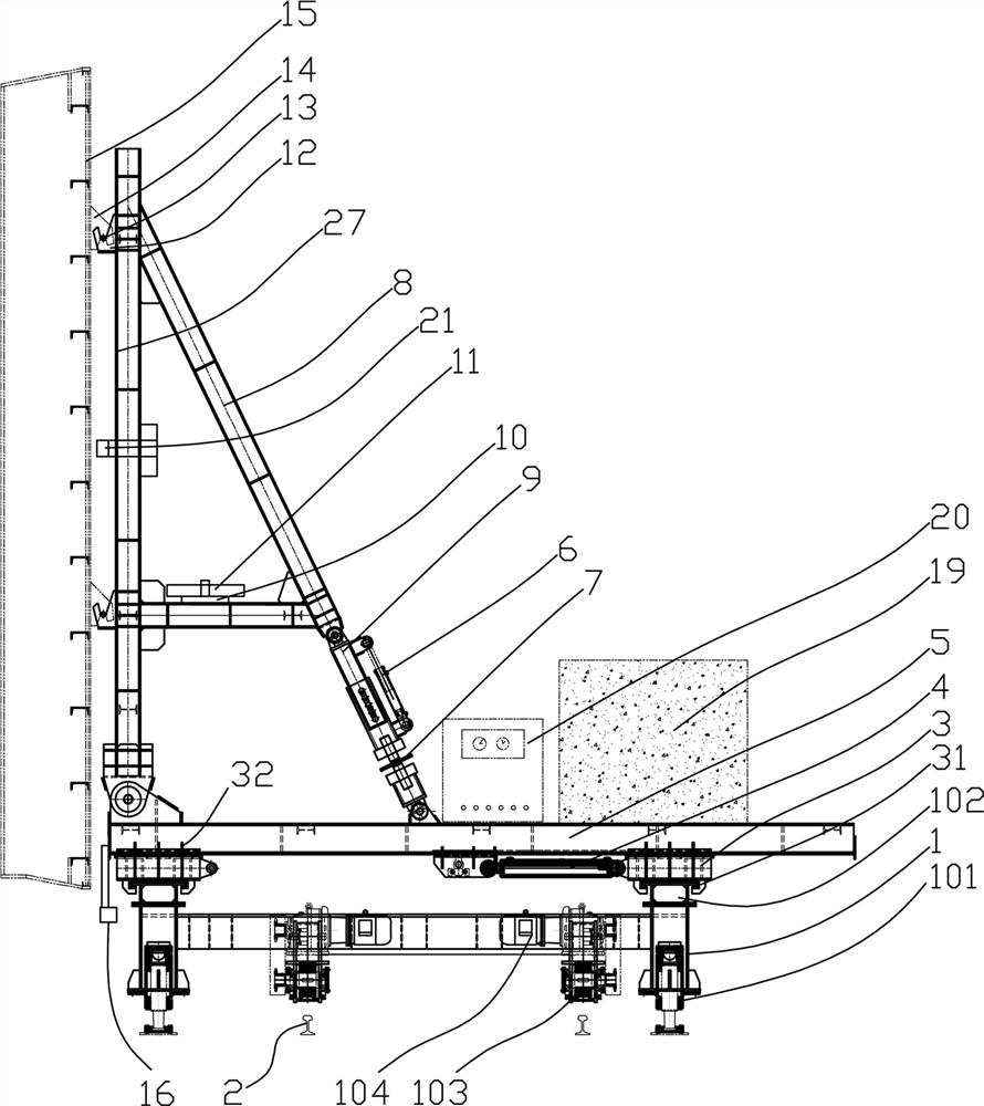
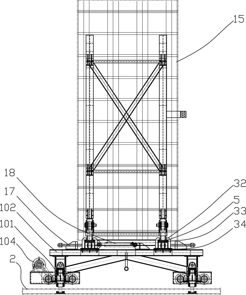
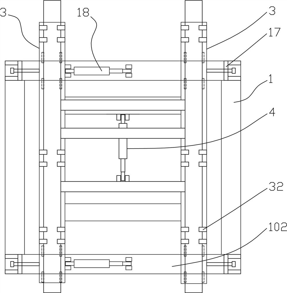
[0071] like Figures 6~10 , a construction method for an automatic control device for loading and unloading heavy structures, comprising the following steps:

[0072] S1. A walking track 2 is set near the installation position, and the walking track 2 passes through at least an installation station and a loading and unloading station; the installation station refers to the position near the installation position for installing the heavy structure 15. The difficulty often encountered is also that the space near the installation location is relatively narrow. The loading and unloading station refers to a relatively open position, which is convenient for the hoisting of the heavy structure 15 .

[0073] The loading and unloading trolley is movably arranged on the walking track 2, the loading and unloading trolley is provided with a bearing seat 12 for connecting with the heavy structure 15, and the loading and unloading trolley is also provided with an adjustment mechanism for adj...

Embodiment 2

[0079] The more detailed steps are: set the auxiliary positioning target 22, and set the auxiliary positioning target 22 near the position to be installed by offsetting the corresponding spatial distance according to the parameter of the spatial distance between the position of the positioning sensor 16 and the installation position. The traveling frame 1 is located at the hoisting position of the traveling track 2, such as Image 6 shown in. The hoisting device hoists the heavy construction 15 , such as the end sealing door of the sunk pipe, onto the loading and unloading frame 8 , so that the barb device 14 is hooked on the bearing pin 13 . After the installation is fixed, the driving device 104 drives the traveling frame 1 to walk along the traveling track 2 to the installation station, the auxiliary positioning target 22 adopts the pattern of concentric circles and radial rays to assist in positioning, and the positioning sensor 16 adopts a photoelectric sensor or a camera...


PUM


Abstract

The invention provides an automatic control device for loading and unloading of heavy structures, comprising a movable loading and unloading trolley, the loading and unloading trolley is provided with a bearing seat for connecting with the heavy structures, and the loading and unloading trolley is also provided with adjusting the heavy structures Spatial position adjustment mechanism; a positioning sensor is provided on the loading and unloading trolley where it is not blocked by heavy structures; an auxiliary positioning target for auxiliary positioning is also provided, which is one of the parameters of the auxiliary positioning target and the installation position of the heavy structure In association with one or more parameters, the auxiliary positioning target is set at a position corresponding to the positioning sensor. By adopting the solution of positioning sensors and auxiliary positioning targets, it is convenient to realize precise positioning using sensors on the premise that heavy structures block the installation position.

Description

technical field [0001] The invention relates to the field of installation and disassembly of heavy structures, in particular to an automatic control device for the installation and removal of heavy structures. Background technique [0002] The heavy structures referred to in this example include structures that are difficult or inconvenient to handle by manpower, such as steel end sealing doors for underground pipes or corridors; fabricated shear walls, fabricated beams, fabricated columns or other fabricated components; large-scale integrated glass curtain wall units, etc. Taking the immersed steel end-sealing door as an example, the current installation mostly adopts the traditional construction method: that is, firstly install the corbel and steel beam, and finally rely on the installed components to position and install the end-sealing door with a spreader and a chain hoist, which is also a lot of heavy construction. main installation method. This construction method r...

Claims


Application Information

Patent Timeline
Patent Type & Authority Patents(China)
IPC IPC(8): B66F9/06B66F9/075B66F9/12B66F9/22E04G21/16E04G21/18
CPCB66F9/06B66F9/0755B66F9/07577B66F9/07554B66F9/12B66F9/075B66F9/22E04G21/162E04G21/1841Y02E10/20
Inventor 刘斌梁丰李海方谢小琴阮明华纪岩王虎臣
Owner CCCC WUHAN HARBOR ENG DESIGN & RES
Learn More