Conveying method of heating furnace in continuous glass toughening furnace

A glass tempering and heating furnace technology, which is applied in glass tempering, glass transportation equipment, glass manufacturing equipment, etc., can solve problems such as easy deformation of the glass surface, achieve obvious effects, improve wave patterns, and increase production capacity.

Pending Publication Date: 2020-11-10
宣城吉鼎玻机械有限公司
View PDF6 Cites 4 Cited by
  • Summary
  • Abstract
  • Description
  • Claims
  • Application Information

AI Technical Summary

Problems solved by technology

[0009] Aiming at the problems existing in the prior art, the present invention is committed to providing a new solution to overcome the "wavy" phenomenon of glass, and specifically provides a method for conveying the heating furnace in a continuous glass tempering furnace to improve the quality of the glass Defects that are easily deformed on the surface, especially for ultra-thin glass, while achieving flat glass, it can also expand its glass production capacity, which is more practical

Method used


Image

  • Conveying method of heating furnace in continuous glass toughening furnace
  • Conveying method of heating furnace in continuous glass toughening furnace
  • Conveying method of heating furnace in continuous glass toughening furnace

Examples


Embodiment 1

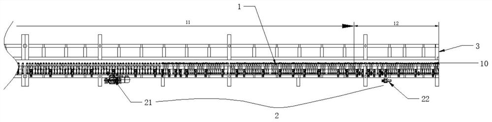
[0035] Such as figure 1Shown is a schematic structural view of a heating furnace in the prior art. The heating furnace of the continuous tempering furnace mainly includes a furnace body, a conveying line 1, a conveying mechanism 2, and a heating device (not shown in the figure); In the heating furnace part of the tempering furnace, an acceleration section 12 will be set near the furnace door 3. The conveyor line 1 of the heating furnace is divided into a flat delivery section 11 and an acceleration section 12. The transmission of the conveyor roller table 10 in the acceleration section is controlled separately by an acceleration motor 22 , The length of the accelerating section 12 matches the glass produced, generally slightly longer than the length of the glass. During specific use, the glass 4 passes through the horizontal conveying section 11 at a constant speed and is heated to the temperature required for tempering, and then the glass 4 as a whole enters the accelerating...

Embodiment 2

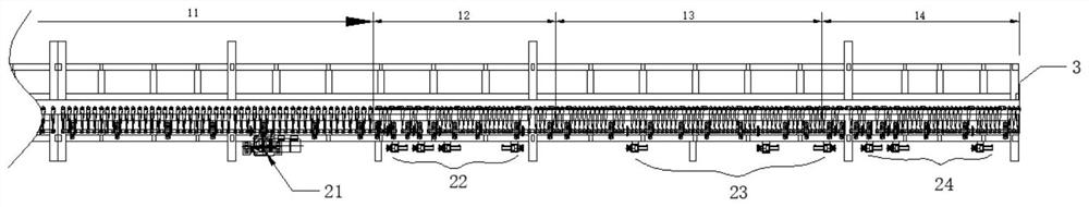
[0056] Compared with Embodiment 1, in this embodiment, as image 3 As shown, a sub-acceleration section 14 is added behind the fast section 13, and the sub-acceleration section 14 is controlled by the sub-acceleration motor 24 to convey the speed.

[0057] When this embodiment is actually used, it is divided into two situations, such as Figure 6 As shown, when the thickness of the glass is >2.5mm, the flat speed section 11, the acceleration section 12, and the fast section 13 all run at a flat speed, and the glass travels to the sub-acceleration section 14, and the speed changes after entering the sub-acceleration section 14 as a whole, and the transmission speed is accelerated to leave Sub-acceleration section 14 comes out of the furnace, and after the glass leaves sub-acceleration section 14, sub-acceleration section 14 returns to its original speed. For thicker glass, the running speed of the roller conveyor has little effect on glass deformation, and only sub-acceleration...


PUM

PropertyMeasurementUnit
surface smoothnessaaaaaaaaaa

Abstract

The invention provides a conveying method of a heating furnace of a continuous glass toughening furnace, and belongs to the field of glass toughening. According to the method, a heating furnace conveying line is divided into a normal-speed section, an acceleration section and a rapid section, wherein in the normal-speed section, the glass is driven to be conveyed at a constant speed at the speed of V flat; in the rapid section the glass is driven to be conveyed at a constant speed at the speed of V<rapid>, V<rapid> being larger than V<normal>; and in acceleration section, variable-speed conveying of the glass is controlled, and the glass is limited at the temperature required by heating to tempering in the rapid section. According to the invention, the accelerating section on the conveyingline of the existing heating furnace is advanced, and meanwhile, the quick section is added behind the accelerating section, so that the glass is limited at the temperature required by the quick section to be heated to be tempered, i.e., the glass is completely heated in the quick moving process and moves in a quick passing manner before being heated to a softening point; as a result, the deformation amplitude of the glass is effectively reduced, so that the defect that raised grains are likely to appear on the surface of the glass is overcome, the effect is more obvious especially for ultrathin glass with the glass thickness smaller than or equal to 2.5 mm, and the flatness of the glass can reach 0.2 mm or below.

Description

technical field [0001] The invention belongs to the field of glass tempering, and relates to a continuous glass tempering furnace, in particular to a conveying method for the heating furnace. Background technique [0002] The glass tempering furnace uses physical methods to form a compressive stress layer on the glass surface and a tensile stress layer inside; when the glass is subjected to external force, the compressive stress layer can offset part of the tensile stress to avoid glass breakage, thereby achieving the goal of improving glass strength. Purpose. Glass tempering furnaces are mainly divided into reciprocating tempering furnaces and continuous tempering furnaces. Reciprocating tempering furnaces occupy a small area, but have low production efficiency and low capacity, and are only suitable for small-scale glass production; continuous tempering furnaces are relatively , high production efficiency, low energy consumption, and can guarantee higher performance requi...

Claims


Application Information

Patent Timeline
Patent Type & Authority Applications(China)
IPC IPC(8): C03B35/16C03B27/012
CPCC03B35/166C03B27/012
Inventor 冯珊
Owner 宣城吉鼎玻机械有限公司
Why Eureka
Try Eureka