Supercharge Your Innovation With Domain-Expert AI Agents!

Needle beam drive structure of needling machine

A driving structure and technology for acupuncture machines, which are used in acupuncture machines, textiles and papermaking, non-woven fabrics, etc., can solve the problems of processing difficulties such as strict precision requirements, long drive shafts, and difficult to guarantee precision, and achieve a good balance. The effect of counterweight movement, reducing work intensity, and ensuring the effect of connection

Active Publication Date: 2022-07-22
JIANGSU YINGYANG NONWOVEN MASCH CO LTD
View PDF22 Cites 0 Cited by
  • Summary
  • Abstract
  • Description
  • Claims
  • Application Information

AI Technical Summary

Problems solved by technology

[0005] The aforementioned driving structure of the needle looms in the prior art, including the patent mentioned above, may be affected and / or constrained by the traditional concept, and the driving shaft (ie, the "main shaft") is uniformly arranged in the form of a whole, However, the applicant's long-term maintenance records for manufacturers of needle looms show that the lengthy drive shaft has at least the following disadvantages: one is that the processing difficulty in the manufacturing process such as precision requirements is very strict, that is, It not only greatly increases the difficulty of manufacturing, but also makes it difficult to guarantee the accuracy; second, because the drive shaft is in the form of a whole, the strength in use is affected to a certain extent, for example, there will be deflection, which will affect the eccentric connecting rod to drive the needle beam up and down through the guide post The stability of the movement; the third is that the initial installation and daily maintenance and installation such as replacing the bearing are very troublesome due to the long and heavy drive shaft; the fourth is that once damaged, it can only be discarded as a whole. Maintenance costs, on the other hand cause serious waste of resources

Method used


Image

  • Needle beam drive structure of needling machine

Examples


Embodiment Construction

[0019] In order to be able to understand the technical essence and beneficial effects of the present invention more clearly, the applicant will describe in detail below by way of examples, but the description of the examples is not intended to limit the solution of the present invention. Equivalent transformations that are only formal but not substantial should be regarded as the scope of the technical solutions of the present invention.

[0020] In the following description, all concepts related to the directionality or orientation of up, down, left, right, front and back are based on figure 1 In terms of the position and state, it cannot be understood as a special limitation on the technical solution provided by the present invention.

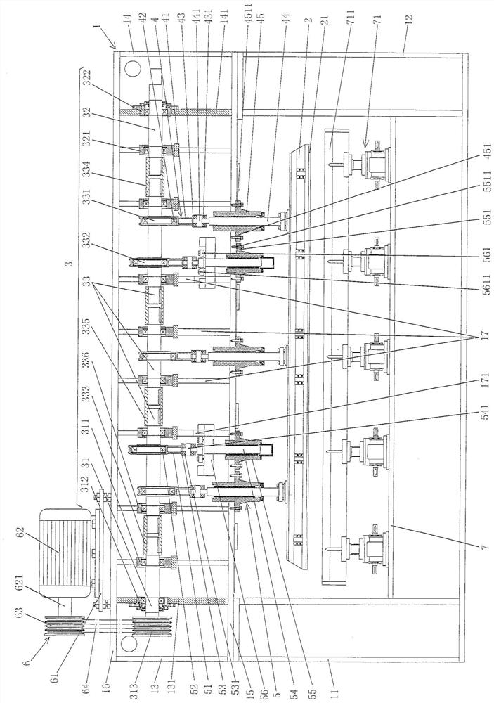
[0021] See figure 1 , shows the frame 1 and the needle beam 2 of the structural system of the acupuncture machine. The frame 1 includes a lower left box 11, a lower right box 12, an upper left box 13 and an upper right box 14. The lower left b...


PUM


Abstract

A needle beam driving structure of a needle punching machine includes a frame and a needle beam, the frame includes left and right lower boxes and left and right upper boxes; the needle beam driving structure includes a driving shaft, a link mechanism and a balance mechanism. : There is a partition between the upper connecting beam of the upper box and the lower connecting beam of the upper box. The drive shaft includes a power input shaft, an end support shaft and a set of connecting rod drive shafts. The middle of the power input shaft is supported on the partition and the left end It is supported on the upper left box body wall, the middle part of the end support shaft is supported on the partition plate, the right end is supported on the right upper box body wall plate, a group of connecting rod drive shafts are supported on the partition board, and two adjacent connecting rod drive shafts are supported on the partition board. They are connected to each other. A group of connecting rod drive shafts has a connecting rod cam at the position corresponding to the connecting rod mechanism, and a balance block drives the connecting rod cam at the position corresponding to the balance mechanism. The connecting rod mechanism is arranged on the connecting rod cam, and the balance The mechanism is arranged on the cam of the balance weight driving link. Ensure processing quality and facilitate manufacturing; ensure the stability of movement; reduce work intensity.

Description

technical field [0001] The invention belongs to the technical field of non-woven machinery, in particular to a needle beam driving structure of a needling machine. Background technique [0002] The aforementioned needling machines include pile needling machines (also called jacquard pile needling machines, pile jacquard needling machines or needle-punching jacquard pile machines). Acupuncture machines are well known in the industry, and are often seen in published Chinese patent documents, such as CN101492861B (automatic multifunctional acupuncture machine), CN102373579B (endless acupuncture machine), CN102677397B (structural improvement) dual-shaft acupuncture machine), CN102677398A (dual-shaft acupuncture machine), CN102808290B (drum type acupuncture machine), CN106087258B (double-sided counter-needling machine), CN105734836A (a low-noise acupuncture machine), CN106087259A ( A high-speed dual-axis guide ectopic needle punching machine) and CN106988023A (a small-diameter f...

Claims


Application Information

Patent Timeline
Patent Type & Authority Patents(China)
IPC IPC(8): D04H18/02
CPCD04H18/02
Inventor 范立元
Owner JIANGSU YINGYANG NONWOVEN MASCH CO LTD
Features
  • R&D
  • Intellectual Property
  • Life Sciences
  • Materials
  • Tech Scout
  • Unparalleled Data Quality
  • Higher Quality Content
  • 60% Fewer Hallucinations
Learn More