Supercharge Your Innovation With Domain-Expert AI Agents!

A heat sink structure and stamping processing equipment thereof

A technology of stamping processing and cooling fins, applied in metal processing equipment, heat exchange equipment, manufacturing tools, etc., can solve the problems of inability to replace fins, unfavorable maintenance costs of cooling fins, etc., achieve high processing efficiency, convenient replacement, and guaranteed maintenance cost effect

Active Publication Date: 2021-03-26
深圳市维鼎精密五金有限公司
View PDF11 Cites 0 Cited by
  • Summary
  • Abstract
  • Description
  • Claims
  • Application Information

AI Technical Summary

Problems solved by technology

[0003] The existing technical solutions above have the following defects: the heat sink body and the fins are integrally formed, and if the heat sink is damaged, the fins cannot be replaced, so the heat sink needs to be replaced as a whole, which is not conducive to ensuring the maintenance cost of the heat sink

Method used


Image

  • A heat sink structure and stamping processing equipment thereof
  • A heat sink structure and stamping processing equipment thereof
  • A heat sink structure and stamping processing equipment thereof

Examples


Embodiment 1

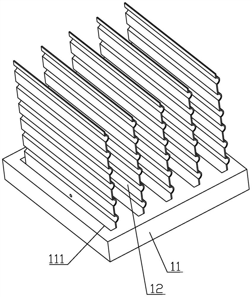
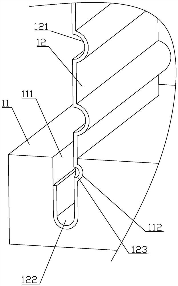
[0035] refer to figure 1 , is a heat sink structure disclosed in the present invention, including a body 11 and a plurality of fins 12 arranged on the body 11 . The main body 11 is in the shape of a rectangular plate, and its length direction is horizontal. The upper surface of the main body 11 is provided with a long slot 111 for insertion. The opening of the long slot 111 is in the shape of a rectangular strip. The direction is vertical, and there are multiple insertion slots 111 , and the insertion slots 111 are evenly arranged along the length direction of the body 11 . to combine figure 2 As shown, one side of the insertion long slot 111 is parallel to the inner side wall of its own length direction and is provided with a snap-in inner slot 112. The inner wall of the snap-in inner slot 112 is arc-shaped, and the opening of the snap-in inner slot 112 is round. shape. The fins 12 are in the shape of a rectangular sheet and are stamped from an aluminum sheet. They are ve...

Embodiment 2

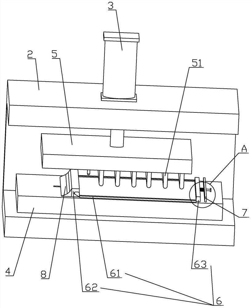
[0039] refer to image 3 , is a heat sink structure stamping processing equipment disclosed in the present invention, including a frame 2, a hydraulic cylinder 3, a workbench 4 and a stamping seat 5, the frame 2 is a frame 2 structure with a U-shaped vertical section, and its The two ends are horizontally facing the same direction, and the hydraulic cylinder 3 is an existing linear drive device. The hydraulic cylinder 3 is arranged on the frame 2 and fixed to the upper surface of the frame 2, and the end of the piston rod of the hydraulic cylinder 3 runs through it vertically and sequentially. The upper surface of the frame 2 and the inner top surface of the frame 2 are also located in the frame 2 . The workbench 4 is a rectangular platform, which is arranged in the frame 2, and the bottom surface of the workbench 4 is fixed to the inner bottom surface of the frame 2. In addition, the workbench 4 is arranged on the lower side of the piston rod end of the hydraulic cylinder 3. ...


PUM


Abstract

The invention relates to a cooling fin structure and punching processing equipment thereof, and relates to the technical field of cooling fin processing. The cooling fin structure comprises a main body and fins arranged on the main body, wherein the edges, close to the main body, of the fins are bent to form U-shaped bending parts; clamping bulges bulged and deformed toward the direction far awayfrom the edges of the bending parts are arranged on the bending parts; plug-in elongated slots in plug-in fit with the bending parts are formed in the main body; clamping inner slots for holding the clamping bulges when the bending parts are plugged into the plug-in elongated slots are formed in the inner walls of the plug-in elongated slots; and the bending parts are abutted against the inner walls of the plug-in elongated slots. The cooling fin structure provided by the invention has an effect on conveniently replacing the fins, and the maintenance cost of a cooling fin is guaranteed favorably.

Description

technical field [0001] The invention relates to the technical field of heat sink processing, in particular to a heat sink structure and stamping processing equipment. Background technique [0002] Heat sink is a device for dissipating heat from electronic components that are prone to heat in electrical appliances. It is mostly made of aluminum alloy, copper, etc. The power supply tube in the TV, the row tube, and the power amplifier tube in the power amplifier must use heat sinks. Generally, the heat sink should be coated with a layer of heat-conducting silicone grease on the contact surface between the electronic components and the heat sink during use, so that the heat emitted by the components can be more effectively transferred to the heat sink, and then dissipated into the surrounding air through the heat sink. The existing Chinese patent with the notification number CN105377004A discloses a heat sink, which includes a heat sink body and a plurality of heat conducting ...

Claims


Application Information

Patent Timeline
Patent Type & Authority Patents(China)
IPC IPC(8): B21D13/02B21D43/00B21D53/04
CPCB21D13/02B21D43/003B21D53/04
Inventor 邹文学袁金红
Owner 深圳市维鼎精密五金有限公司
Features
  • R&D
  • Intellectual Property
  • Life Sciences
  • Materials
  • Tech Scout
  • Unparalleled Data Quality
  • Higher Quality Content
  • 60% Fewer Hallucinations
Learn More