Ground subsidence value monitoring device and method

A ground subsidence and monitoring device technology, which is applied in the direction of basic structure testing, construction, and basic structure engineering, can solve the problem of low precision and achieve an effect that is conducive to accuracy

Pending Publication Date: 2020-11-10
CITIC GUOAN CONSTR GRP CO LTD
View PDF0 Cites 1 Cited by
  • Summary
  • Abstract
  • Description
  • Claims
  • Application Information

AI Technical Summary

Problems solved by technology

However, different from other methods, the above monitoring method using sinking rods has the problem of low accuracy

Method used


Image

  • Ground subsidence value monitoring device and method
  • Ground subsidence value monitoring device and method

Examples


Embodiment 1

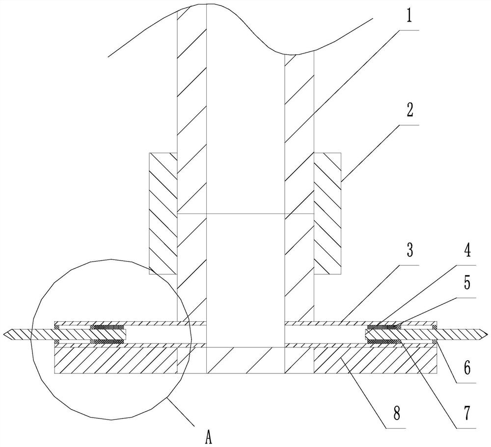
[0042] Such as figure 1 and figure 2 As shown, the ground subsidence value monitoring device includes a sinking rod 1, the bottom end of which is a tubular structure with a blind end, and also includes a plug assembly arranged at the bottom end of the sinking rod 1;

[0043] The plug-in assembly includes a cylinder section 3 and an insertion rod 4, one end of the cylinder section 3 is fixedly connected to the sinking rod 1, and the inner space of the cylinder section 3 communicates with the inner space of the sinking rod 1; the insertion rod 4 is located at The inner side of the cylinder section 3, and the length direction of the insertion rod 4 is parallel to the length direction of the cylinder section 3, and the insertion rod 4 can slide along the length direction of the cylinder section 3 in the cylinder section 3;

[0044] A sealing packing 5 is also provided between the end of the insertion rod 4 close to the sinking rod 1 and the inner wall of the insertion rod 4, and...

Embodiment 2

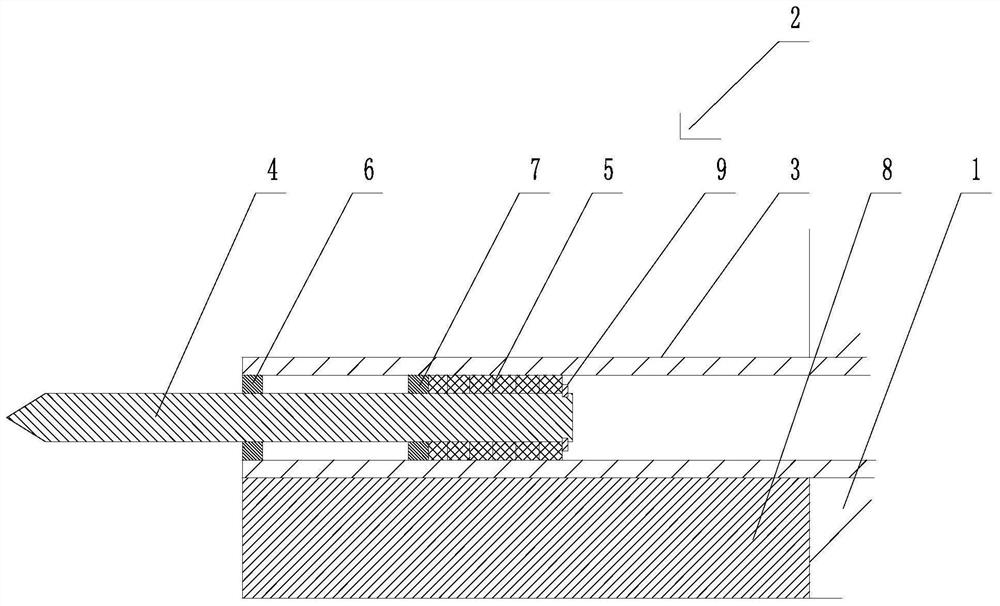
[0057] Such as figure 1 and figure 2 As shown, the present embodiment is further limited on the basis of embodiment 1:

[0058] As a specific embodiment of a restraining device and a limiting device with a simple structure and easy assembly, it also includes a first stop ring 6 fixed on the free end of the cylinder section 3 and located inside the cylinder section 3; The second retaining ring 7; also includes an elastic retaining ring 9 for the shaft installed on the insertion rod 4;

[0059] The sealing packing 5 is clamped between the shaft circlip 9 and the second retaining ring 7, and the shaft retaining ring 9 and the second retaining ring 7 form the position-limiting device;

[0060] The second retaining ring 7 is located between the circlip 9 for the shaft and the first retaining ring 6, and when the insertion rod 4 slides out from the free end of the barrel section 3, it passes through the inner end surface of the first retaining ring 6 and the second retaining ring...


PUM


Abstract

The invention discloses a ground subsidence value monitoring device and method. The ground subsidence value monitoring device comprises a subsidence rod, and further comprises an insertion assembly. The insertion assembly comprises a barrel section and an inserting rod, and one end of the barrel section is fixedly connected with the subsidence rod; the inserting rod is located on the inner side ofthe barrel section, the length direction of the inserting rod is parallel to the length direction of the barrel section, and the inserting rod can slide in the barrel section in the length directionof the barrel section; and sealing filler is further arranged between the end, close to the subsidence rod, of the inserting rod and the inner wall of the inserting rod and used for achieving axial sealing of a gap between the inserting rod and the barrel section. A limiting device used for limiting the position of the sealing filler in the length direction of the inserting rod is further included; and a restraining device used for restraining the extending length of the inserting rod relative to the free end of the barrel section is further included. The method is based on the device. By adopting the device and method provided by the scheme, the precision of bottom face subsidence monitoring based on the subsidence rod can be optimized, and meanwhile, the device and method have the characteristic of convenience in installation.

Description

technical field [0001] The invention relates to the technical field of foundation pit construction, in particular to a ground subsidence value monitoring device and method. Background technique [0002] The foundation pit generally refers to the earth pit excavated at the design position of the building foundation according to the elevation of the building foundation and the plane size of the foundation. For foundation pit construction, the foundation pit support mechanism is used as a temporary structure and a safety protection structure to prevent collapse during foundation pit construction. At the same time, during the excavation and construction of the foundation pit, the precipitation of the foundation pit needs to be considered. [0003] The excavation and dewatering of the above foundation pits will cause adverse effects on the surrounding geology, one of which is: it will cause the surrounding ground subsidence. Therefore, in the existing construction, the ground s...

Claims


Application Information

Patent Timeline
Patent Type & Authority Applications(China)
IPC IPC(8): E02D33/00
CPCE02D33/00
Inventor 陈红平周亮郑洪友刘会实曾祥燕王新乐
Owner CITIC GUOAN CONSTR GRP CO LTD
Why Eureka
Try Eureka