Auxiliary mounting device for building construction

An installation device and building construction technology, which can be used in construction, building structure, and building material processing, etc., and can solve problems such as worker fatigue, hidden safety hazards, and dangers of high-altitude operations.

Inactive Publication Date: 2020-11-10
陈祥德
View PDF6 Cites 5 Cited by
  • Summary
  • Abstract
  • Description
  • Claims
  • Application Information

AI Technical Summary

Problems solved by technology

[0005] In order to overcome the existing technology, the shear wall is made of reinforced concrete. Before that, the formwork needs to be installed in advance. After the formwork is erected on the ground, a large number of support frames are needed to reinforce and stabilize it. When installing the formwork support, First, the horizontal beams should be clipped into the threaded steel bars of the vertical beams one by one, and then the linear locks should be clamped on the two parallel horizontal beams, and then the linear locks should be tightened with nuts, so that the linear locks can connect the two parallel horizontal beams Locking, the installation process is cumbersome and inefficient. In addition, in the manual installation process, it is necessary to carry a large number of horizontal beams and linear locks from the ground to a high place for installation. The horizontal beams and linear locks are all steel structures, which are heavy and easy to install. It will lead to the fatigue of workers, and it is very dangerous for workers to work at heights under fatigue conditions, accidents are prone to occur, and there are great potential safety hazards. The technical problem of the present invention is to provide an auxiliary installation device for construction

Method used


Image

  • Auxiliary mounting device for building construction
  • Auxiliary mounting device for building construction
  • Auxiliary mounting device for building construction

Examples


Embodiment 1

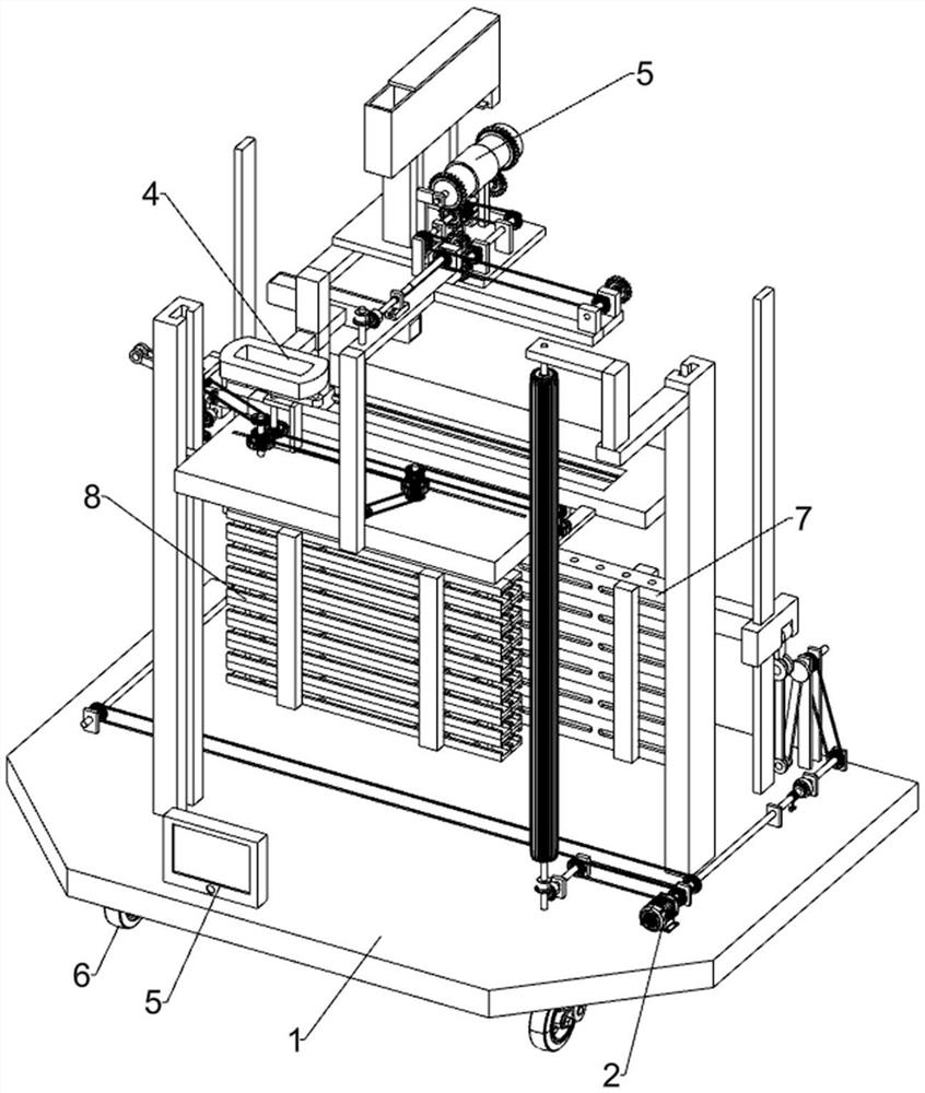
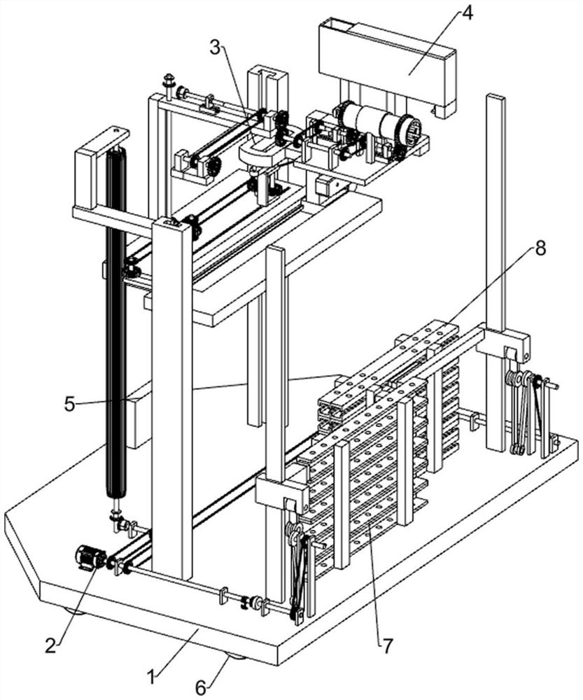
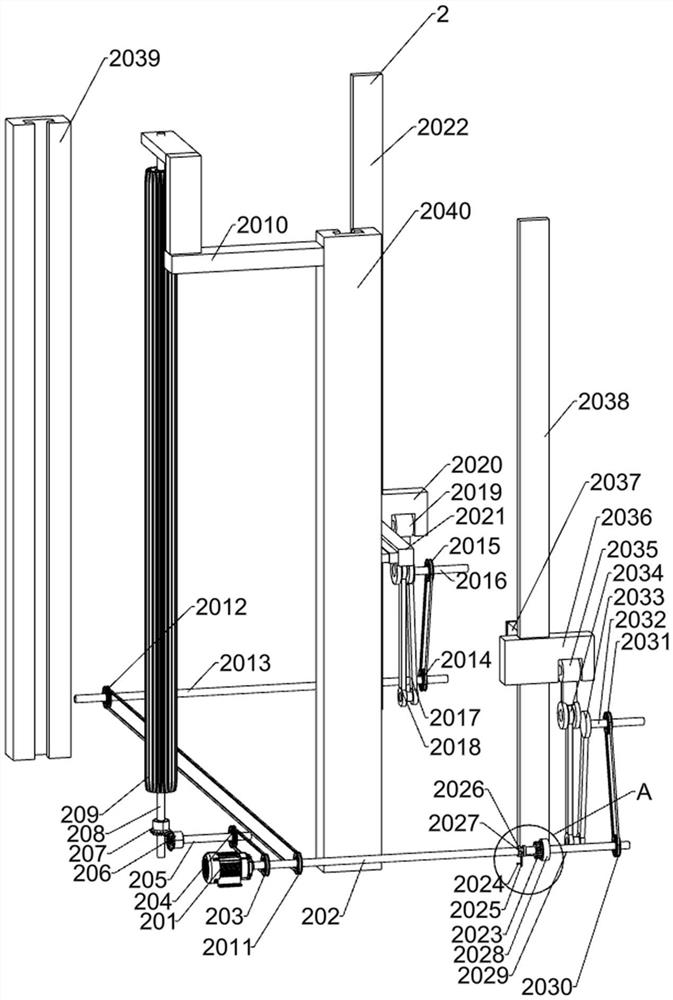
[0030] An auxiliary installation device for building construction, such as Figure 1-9 As shown, it includes an underframe 1, a transom lock transport mechanism 2, a transom lock installation mechanism 3, a transom fixing mechanism 4, a control panel 5, an electric wheel 6, a linear lock 7 and a transom 8; Control panel 5, linear lock 7 and transverse beam 8; a beam lock transportation mechanism 2 is arranged above the bottom frame 1; an electric wheel 6 is arranged under the bottom frame 1; the cross beam lock transportation mechanism 2 is connected with the horizontal bar lock installation mechanism 3; The bar lock installation mechanism 3 is connected with the beam fixing mechanism 4 .

[0031]When preparing for work, first place the linear lock 7 and the transverse beam 8 on the top of the chassis 1, then manipulate the control panel 5 to control the electric wheel 6 to drive the device to move to the front of the template that needs to be installed and fixed. The beam 8 ...


PUM


Abstract

The invention relates to the field of building construction, in particular to an auxiliary mounting device for building construction. The technical problem is to provide the auxiliary mounting devicefor building construction. .According to the technical scheme, the auxiliary mounting device for building construction comprises a bottom frame, a transverse beam lock conveying mechanism, a transverse bar lock mounting mechanism, a transverse beam fixing mechanism and the like; and electric wheels are arranged below the bottom frame. According to the device, during use, two transverse beams are automatically transported to the positions needing to be subjected to mounting, then the two transverse beams are automatically located on the same horizontal line and are in contact with each other tobe clamped into threaded steel bars of a form, a linear lock is automatically clamped into the upper portions of the two transverse beams, and nuts are automatically screwed into threaded steel barsof the linear lock and the two transverse beams, so that the two transverse beams are fixed through the linear lock, and during use, the structure is simple, the efficiency is high, workers do not need to work high above the ground, and potential production safety hazards are greatly reduced.

Description

technical field [0001] The invention relates to the field of building construction, in particular to an auxiliary installation device for building construction. Background technique [0002] Shear walls are also called wind-resistant walls, seismic walls or structural walls. Walls in houses or structures that mainly bear horizontal loads and vertical loads caused by wind loads or earthquakes to prevent structural shear damage, also known as seismic walls, are generally made of reinforced concrete, which are divided into plane shear walls and cylinders shear wall. Planar shear walls are used in reinforced concrete frame structures, raised slab structures, and beamless floor systems. In order to increase the rigidity, strength and collapse resistance of the structure, reinforced concrete shear walls can be cast-in-place or prefabricated in some parts. The cast-in-place shear wall and the surrounding beams and columns are poured at the same time, and the integrity is good. ...

Claims


Application Information

Patent Timeline
Patent Type & Authority Applications(China)
IPC IPC(8): E04G21/16E04G17/14B60P3/022B60P7/06B62D63/02B62D63/04
CPCB60P3/00B60P7/06B62D63/02B62D63/04E04G17/14E04G21/16E04G21/162
Inventor 陈祥德
Owner 陈祥德
Why Eureka
Try Eureka