
A nano-magnetic fluid magnetically driven heat pipe

A nano-magnetic and magnetic-driven technology, applied to indirect heat exchangers, lighting and heating equipment, etc., can solve the problems of inconvenient use, restrictions, and easily damaged installation positions of heat pipes, so as to avoid power consumption, effectively dissipate heat, and improve cooling The effect of potency

Active Publication Date: 2021-12-28
XI AN JIAOTONG UNIV
View PDF0 Cites 0 Cited by
  • Summary
  • Abstract
  • Description
  • Claims
  • Application Information

AI Technical Summary

Problems solved by technology

[0004] The purpose of the present invention is to overcome the above-mentioned shortcomings of the prior art and provide a nano-magnetic fluid magnetically driven heat pipe. The present invention is used to solve the technical problems of the prior art that the heat pipe is inconvenient to use, easily damaged and limited by the installation position

Method used


Image

  • A nano-magnetic fluid magnetically driven heat pipe
  • A nano-magnetic fluid magnetically driven heat pipe

Examples


Embodiment Construction

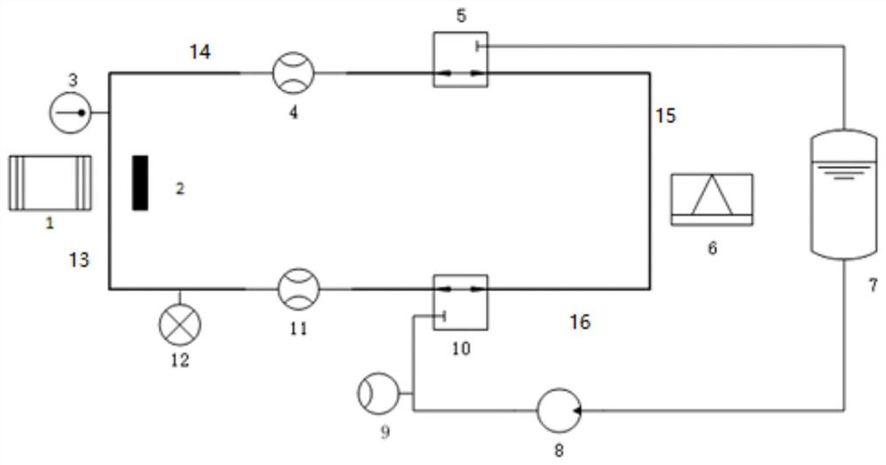
[0032] The present invention is described in further detail below in conjunction with accompanying drawing:

[0033] In the description of the present invention, it should be noted that the terms "center", "upper", "lower", "left", "right", "vertical", "horizontal", "inner", "outer" etc. The indicated orientation or positional relationship is based on the orientation or positional relationship shown in the drawings, and is only for the convenience of describing the present invention and simplifying the description, rather than indicating or implying that the referred device or element must have a specific orientation, or in a specific orientation. construction and operation, and therefore cannot be construed as limiting the present invention; the terms "first", "second", and "third" are used for descriptive purposes only, and cannot be construed as indicating or implying relative importance; in addition, unless otherwise Clearly stipulated and limited, the terms "installation"...


PUM


Abstract

The invention discloses a nano magnetic fluid magnetic drive heat pipe. The heat pipe is provided with a magnetic circuit on one side of the evaporating section, and the heat source and the magnetic circuit are arranged oppositely, so that the fluid in the pipeline is subjected to the magnetic field while being subjected to the thermomagnetic action. The magnetic force generated by the gradient is driven to complete the cycle, and the gradient magnetic field is added through the permanent magnet. On the one hand, it avoids the power consumption of the electromagnet. Convective heat exchange, and use the characteristics of nanoparticles to assist nucleation to strengthen the nucleate boiling and condensation process, so as to realize the heat pipe designed with high heat flow and heat exchange capacity.

Description

【Technical field】 [0001] The invention belongs to the technical field of heat energy exchange, and relates to a nanometer magnetic fluid magnetic drive heat pipe. 【Background technique】 [0002] The heat pipes widely used at present are mainly siphon heat pipes and gravity heat pipes, also known as cored heat pipes and coreless heat pipes. In the evaporation section of the siphon heat pipe, the working liquid in the tube core is heated and evaporated, and the heat is taken away. The heat is the latent heat of evaporation of the working liquid. The steam flows from the central channel to the condensation section of the heat pipe, condenses into a liquid, and releases latent heat at the same time. Under the action of force, the liquid flows back to the evaporation section. In this way, a closed cycle is completed, thereby transferring a large amount of heat from the heating section to the heat dissipation section. For the gravity heat pipe, the reflux of the working liquid c...

Claims


Application Information

Patent Timeline
IPC IPC(8): F28D15/02F28D15/06
CPCF28D15/0266F28D15/06F28D2015/0291
Inventor 唐泽田商逸民贺曦煜张兴邦彭雅婷陈雪江张可
Owner XI AN JIAOTONG UNIV
Features
  • Generate Ideas
  • Intellectual Property
  • Life Sciences
  • Materials
  • Tech Scout
  • Unparalleled Data Quality
  • Higher Quality Content
  • 60% Fewer Hallucinations
Learn More