
Direct-scanning exposure device

An exposure device and direct-drawing technology, applied in the field of direct-drawing exposure devices, can solve the problems of complicated structure, rising device cost, complicated structure of vacuum exhaust, etc., so as to prevent the reduction of exposure precision and the reduction of productivity , Reliable vacuum adsorption effect

Pending Publication Date: 2020-11-10
ADTEC ENG
View PDF1 Cites 1 Cited by
  • Summary
  • Abstract
  • Description
  • Claims
  • Application Information

AI Technical Summary

Problems solved by technology

However, in this configuration, the structure inside the table is complicated, and the structure of its vacuum exhaust is also complicated.
In addition, even if it can barely cope with two to three types of differences in substrate size, it will be too complicated and complicated for more than one difference, and the cost of the device will increase, so it cannot be called a practical device.

Method used


Image

  • Direct-scanning exposure device
  • Direct-scanning exposure device
  • Direct-scanning exposure device

Examples


Embodiment Construction

[0064] Next, modes (embodiments) for carrying out the invention of the present application will be described.

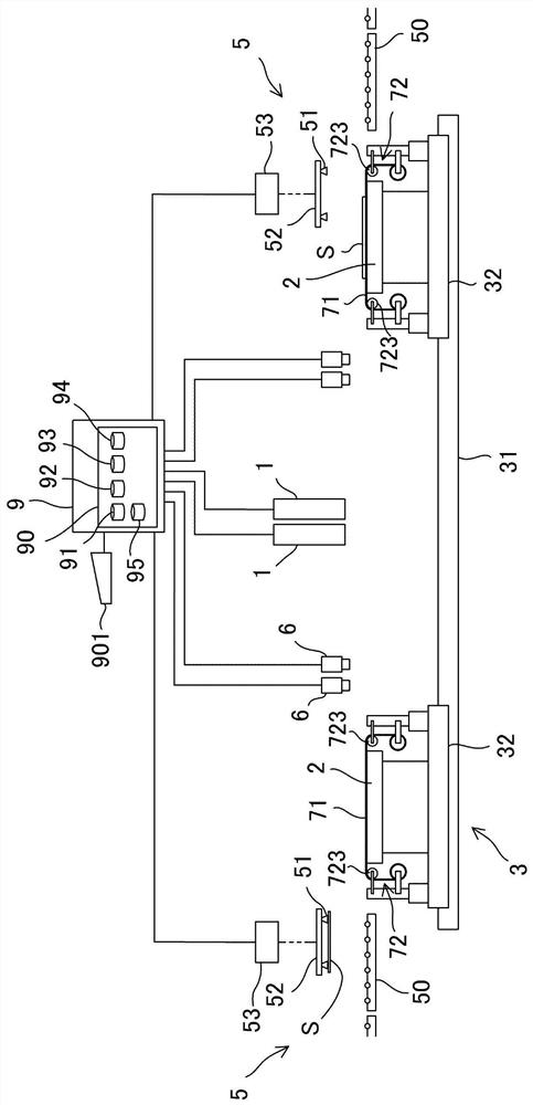
[0065] figure 1 It is a schematic front view of the direct tracing type exposure apparatus of 1st Embodiment. This apparatus is an apparatus for exposing a substrate by irradiating light for an exposure pattern without a mask. Such as figure 1 As shown, the direct drawing exposure apparatus includes: an exposure head 1 for irradiating an exposure area with light for an exposure pattern; a stage 2 on which a substrate S is placed; and a stage 2 on which the substrate S is placed to pass through the exposure area. And the moving handling system3.

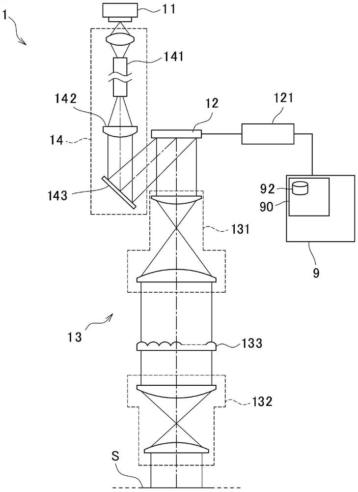
[0066] figure 2 yes figure 1 A schematic diagram of the exposure head 1 mounted on the device. The exposure head 1 has a cylindrical shape as a whole, is arranged in a vertically erected state, and emits light downward. figure 2 It is a schematic diagram showing the internal structure of the exposure head 1 . Such ...


PUM


Abstract

Provided is a practical direct-scanning exposure device capable of sufficiently vacuum-adsorbing substrates of various sizes to a table and exposing the substrates. A substrate (S) is placed on a table (2) on which a large number of vacuum adsorption holes (21) are formed, vacuum adsorption is performed, and when an optical table (2) of an exposure pattern is moved by a conveyance system (3) and passes through an exposure region, light of the exposure pattern is irradiated by an exposure unit (1) and exposed. A large number of vacuum adsorption holes (21) are formed corresponding to the substrate (S) of the maximum size, and a thin plate (71) blocks the vacuum adsorption holes (21) which are not blocked by the substrate (S). The thin plate (71) has suction holes (73) or openings (75, 76),and a thin plate mechanism (72) is positioned so as not to block vacuum suction of the substrate (S). The thin plate (71) and the thin plate mechanism (72) are attached to the table (2) and move integrally with the table (2).

Description

technical field [0001] The invention of the present application relates to a direct tracing type exposure apparatus for exposing a substrate by irradiating light in a predetermined pattern without passing through a mask. Hereinafter, the predetermined pattern of light at the time of exposure is called an exposure pattern. Background technique [0002] Exposure technology for exposing an object having a photosensitive layer formed on its surface to sensitize the photosensitive layer is widely used in the formation of various microcircuits and microstructures, etc. as a main technology of photolithography. A typical exposure technique is a technique in which an image of the mask is projected on the surface of an object by irradiating light to a mask formed with the same pattern as the exposure pattern, whereby the object is irradiated with light of the exposure pattern. [0003] In addition to such an exposure technique using a mask, there is also known a technique of directl...

Claims


Application Information

Patent Timeline
Patent Type & Authority Applications(China)
IPC IPC(8): G03F7/20
CPCG03F7/70391G03F7/70733G03F7/70716G03F7/70291G03F7/2051
Inventor 今井洋之大塚明
Owner ADTEC ENG
Learn More